Another week in the shop
13 Jan 2018
Tags: amp, control panel, the blues deluxe, the red rocker
The most important lesson that I was taught by guitars #3 and #4 was that you should do fit before finish: get everything together in rough form first, check it sits together, tweak it until you’re happy, and then do the “finishing” work. And where finishing is still half the job: sanding things smooth, dying, oiling, final fret finish, and so forth. These two guitars were made of the course of 2017 as I found time away from my day job, and it was just easier for me to take each part through to completion before starting the next. But this meant I made life harder for myself later on when inevitably I found small issues as I assembled each guitar and they were now much harder to deal with, even down to trivial things like fear of scratching the finish as I tweak the electronics. It’s not that you can’t pull it off this way, as I’m really happy with these guitars for the most part, but it just makes your life a lot harder than it need be. This theme dominated my week, and I pass it on as a lesson to anyone else starting out making physical objects for the first time.
With this lesson mind, this week I continued to build the prototype amp with a focus on getting the physical aspects through to rough completion to demonstrate the design before I move on to the electronics side of things. The initial render I posted a while ago of the amp looked like this:
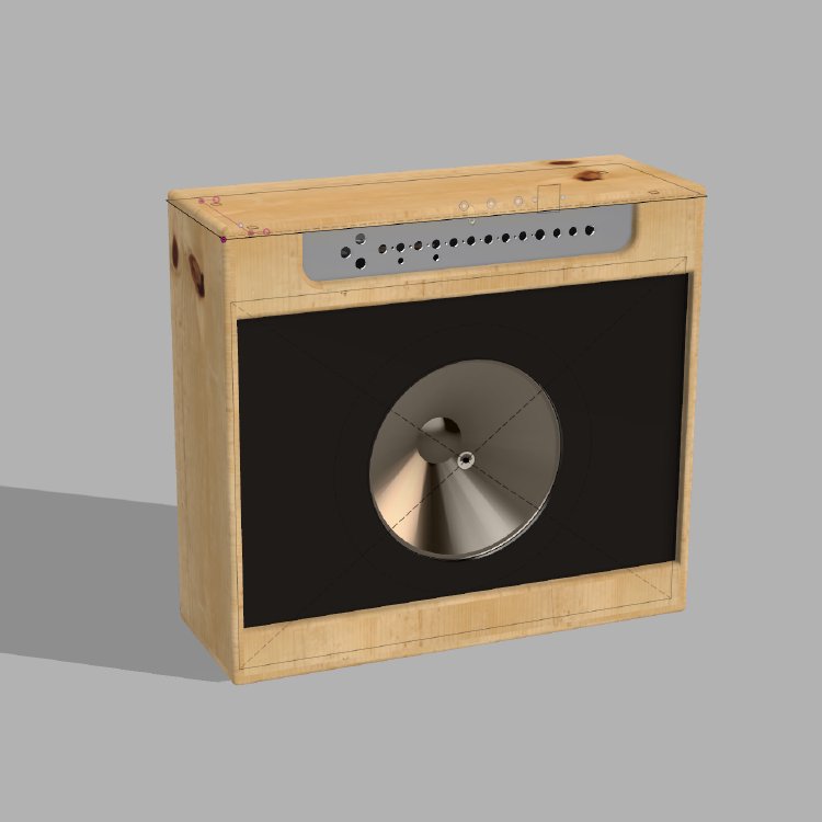
So I was quite pleased when I started putting it together and got to a stage where it looked like this:
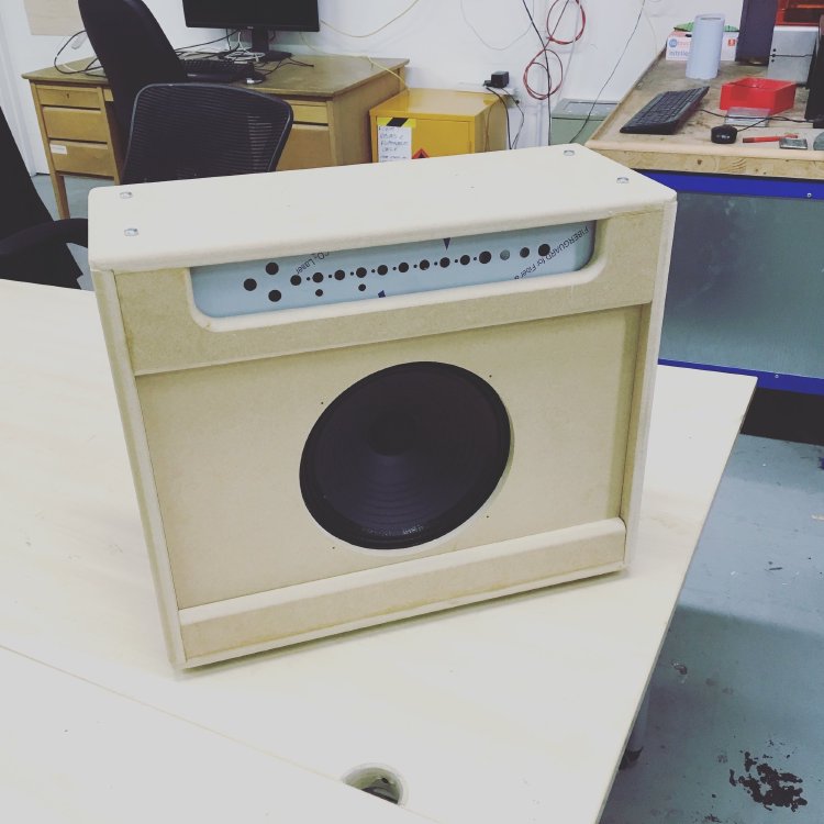
Not bad for my first full design to CAD to CAM to assembly! You’ll see I’m just using MDF here for the body, where as traditionally amps and cabs are made from birch plywood, but that again is just part of prototyping. Birch plywood is quite expensive, so you don’t want to go making your mistakes on that if you can avoid it. For a prototype MDF has enough strength for what I want, comes in the right dimensions: 18mm for the body, 12mm for the speaker baffle.
Part of the reason for the modelling in Fusion 360 was not just to generate the panels, but also let me check all the parts fit. I modelled the chassis I bought, the speaker, and transformers, etc. and put them in place in my model so I could check everything fitted. The reason the speaker baffle is 12mm not 18mm is because otherwise I’d be too close to the power transformer for comfort. If you look at the side profile below, with the front of the amp on the left, you can see all the parts in position. The chassis has the controls on it, so has to be flush with the front, and as does the speaker baffle for obvious reasons. The power transformer is mounted on holes pre-drilled into the chassis I bought, so is forced onto the left, and as such you can see the speaker baffle has to be 12mm to make sure there’s good clearance from the transformer.
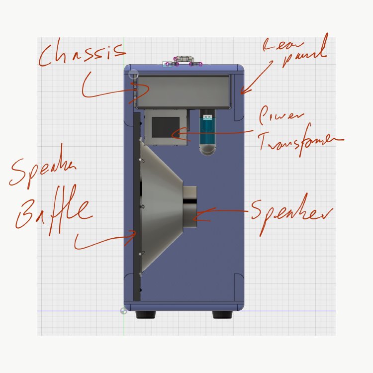
This is why modelling everything, including the bits I’m not going to personally manufacture, in Fusion is great, all the variables like that I can tweak and make sure everything will fit. However, I only modelled the final finished product, I didn’t model the assembly stages, and herein was the lesson of the prototype as early as possible: although things may fit together in final position, you can’t guarantee you can get to that final position!
If you go back to the diagram, you’ll note the chassis is fit quite snuggly between the front and rear panels, which are glued into place. However, with the speaker baffle fitted I can no longer easily slide the chassis up into place, I now have to put it in at an angle so the front goes into the gap between the baffle and the top, and then I rotate the rest of the chassis in. So, dodged a bullet there? No, if you have the power transformer on the chassis (as it will need to be fitted to the chassis before the chassis is fitted to the amp), I can no longer get the front of the chassis into a position where I can rotate it up! So, much like the sofa in Dirk Gently’s Holistic Detective Agency, the chassis does fit, it’s just impossible to get it into that position :)
Thus the lesson here is not just to think about final position at design stage, but also about the steps of assembly too. For this prototype I shall just move the power transformer by drilling new mount points in the chassis to let it sit further back. In production I’d just need to either deepen the who amp by another 10mm or so to let the chassis be put in cleanly, or have the rear panel screwed in rather than glued in, which is a design you see on many amps.
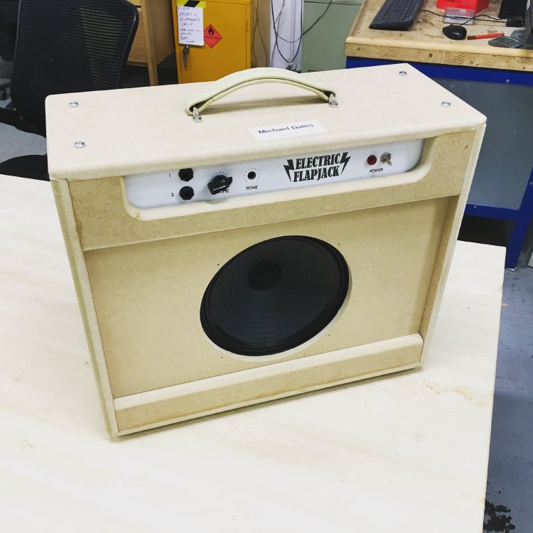
After all that, I also laser cut a prototype front panel for it (more below) and finished fitting the feet and handle, so it’s all looking quite good. Time allowing, I hope to get onto the electronics next week.
Guitar #3 also came back into the shop briefly. This guitar was finished before christmas and has had a bunch of play testing since then, and it came back in for some final fettling. Firstly, I wasn’t happy with the fret ends. Whilst they didn’t catch your hand too much, they still felt a little more present that I wanted, so I took another pass at the fret ends and made them lovely and smooth. I also took this opportunity to adjust the truss rod again now that it’s been together for a while under tension.
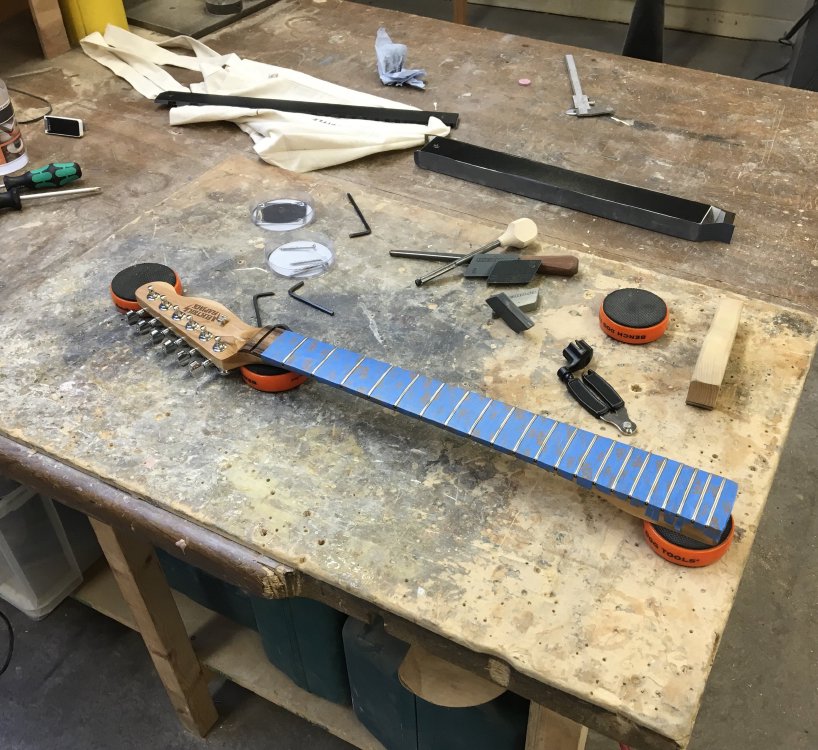
Again, to my opening point, this was made more fiddly by having oiled the neck already and not wanting to damage that finish. But it’s now all done, and I can declare success on my first full neck build being finally finished.
I also decided I wasn’t happy with the quality of my soldering on this one compared to guitar #4, so I went back and strengthened up some of the joints. Soldering is something I’m continually trying to improve on, and practice really does help improve your skills here.
Finally I did a little work in Adobe Illustrator (not a tool I have had much cause to use before). I generated both the design for the control panel and a small flyer (more on which next week I suspect).
Ideally I’d have done the panel design in Fusion 360 and used that to generate the laser cutter instructions, but I didn’t for two reasons. Firstly, at Makespace the laser cutters are plugged into dedicated PCs, and driving them directly isn’t encouraged, thus I’d need to generate vector files rather than tool paths to load into the laser cutter software anyway, so the CAM section of Fusion is no use for me in this case. Secondly, the logo for Electric Flapjack is already in Illustrator, and my brief attempt at importing it into Fusion was frustrating, so I wimped out on grounds of time (something I’ll revisit at a later date though).
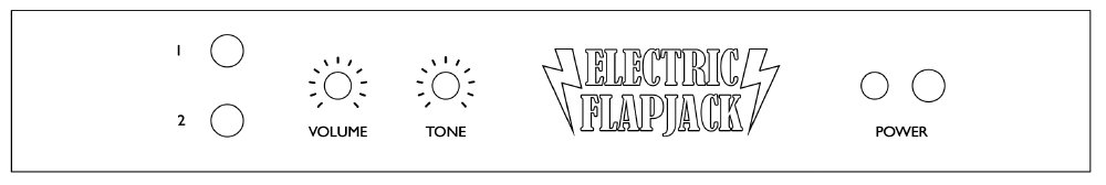
For those interested, I didn’t do the tick marks on the volume and tone controls by hand: I found a website called scale-o-matic designed for making control faces for potentiometers. You give it a bunch of parameters and it’ll generate an EPS file which you can easily import into tools like Illustrator. There truly is a website for everything out there.
Having made the design, I then got some laminated perspex and use the laser cutter to both cut the panel out and etch in the labels. The final bit needs a bit of tweaking, but overall as a rough draft fits in place, and I can do a nicer one in the finishing phase!