A week in the shop
8 Apr 2018
This week I’ve been trying to regain momentum. Between the issues with the CNC router that derailed me, and being under the weather for most of last week, I started this week with a strong sense of not having made much progress, so this week has mostly been about trying to regain traction.
The CNC router at Makespace is still a bit of an unknown, but the fine people there have been digging in more, including doing full checks on the power supply in the workshop, and how it behaves when other machines are turned on, etc. That all looks clean, so it could start to be a software bug in the router perhaps. That said, the cables on the machine are all a bit the worse for wear, so we’re going to replace them. Turns out our CNC machine uses a 50 pin SCSI connector for the controller to talk to the motors, which is quite weird. But a new one shall be ordered shortly. But for now, I think it’s just cautiously back to business as usual.
At the end of last week I got to the point I wanted to be about three weeks ago now, where I’d cut the parts for a prototype run for the neck for the pair of offsets I’m making. The first prototype hadn’t glued properly, so this was a second one to try again. Given I’ve made necks before, why am I prototyping? The reason is that I’m trying a new design with a nicer truss rod access, and I’m trying to glue the fretboard on after shaping rather than before, as that makes things like shaping the headstock transition easier, as I can rough that bit on the CNC router.
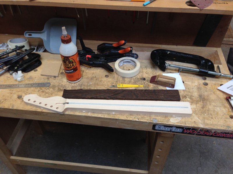
This time I had a new thing to deal with: thin bits of wood (anything under 7 or 8mm in my experience) will have a tendency to warp naturally, and so it was with the wenge fretboard I’d thicknessed just a couple of days earlier. Whilst I kept it pressed under one of the body blanks, that didn’t help combat it’s desire to want to be curved along its length. Normally I’d have made the fret slots before gluing the board to the neck, but given it wasn’t straight I couldn’t do that, as the curvature would be enough to throw of the slot positions that I etch with the laser cutter, as that process assumes a perfectly flat bit of wood.
So instead I just re-ordered things. I glued the fretboard onto the neck without the fret slots, following the technique I used last time, but without the salt, and it worked fine. The reason for trying the salt was that it would stop the fretboard and neck slipping out of position as I clamped them down, but I just used some small spring clamps (like those spring clip clothes pegs, but a little bigger) to hold the two pieces in place whilst I did proper clamps, and that was enough to ensure a good alignment.
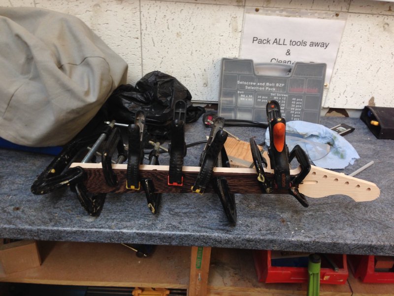
Thankfully this time the seam between the two pieces was nice an tight. I’m still not sure the salt was to blame vs defects in the finishing last time, but either way, it’s clearly not needed for what I’m doing, and saves me having to try expense salt as a building material I guess. I was then able to put the entire neck into the laser cutter to do the fret slot etching, and had a nice calm hour or two whilst I cut them to the final depth by hand with a saw.
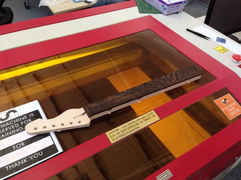
After that, side inlays went in, and for the top inlays rather than use plastic pearl style dots I’m going to try vintage style clay dots, which hopefully I can report back on next week. Once the dots are in I can then carve the neck profile (again by hand) and radius the fretboard.
I wanted to start cutting the bodies this week, but I had a nagging paranoia about spacing of the control cavity on the Offset body, so I set about to remove my paranoia. Most of the time when something goes wrong, it’s usually because I measured and cut, rather than measured, measured, and then cut. I really can’t emphasise that enough to anyone thinking about building guitars, or indeed anything physical. It sounds glib, but it really is the most common cause of mistakes, so if you have a nagging voice in year head worrying about something to do with measuring, it’s always worth paying attention.
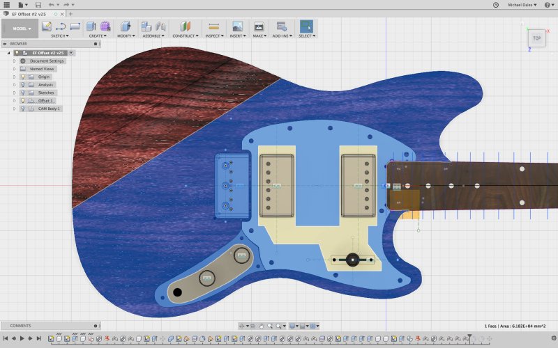
If we look at an earlier picture of the Offset design I’m making:
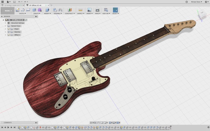
You’ll note that the seam between the pick-guard and the control plate isn’t very neat. To be fair, it’s also not very neat one some of the older Mustang’s I’ve looked at, but we should be doing better than that. It’s important to get this right not just for visual appearance though, the joint there will define the angle at which the control plate sits, which will define whether it actually sits neatly over the cavity underneath the control plate where all the controls are wired; if you get this wrong there’s a risk that you’ll see a slight gap at the edge of the plate, which would be unacceptable.
To solve this, I needed to do get a better model of the control plate itself. I’m making my own pick-guards, so I can make the seam on that side however I like, but the control plates I’ve bought in, and so I have to make sure what I create matches with them. Unlike say a Telecaster control plate, which just has a semicircle profile for the point where it meshes with the pick-guard, the Mustang control plates have a flowing set of curves for the same point; this is pretty, but as a designer trying to model one it is quite annoying, as nowhere is it written down how those curves are defined.
My first attempt to model them was to just measure the heck out of the control plate as much as I could with some calipers. There’s no straight edges on this thing at all, so it’s really quite hard to measure manually, but I gave it my best shot. I then fed all those measurements into Fusion 360 and tried to see if I could get something that was close.
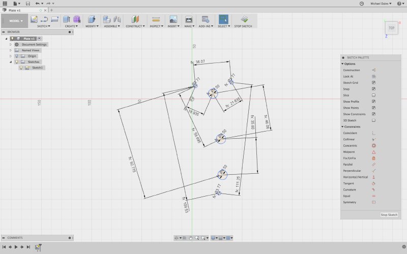
You can see this is a bit of a mess, and got much worse as I added more detail, and despite that it just wasn’t accurate enough. Because I need to manage lots of relationships here you end up with compound errors, so whilst the bits at the top weren’t too badly positioned, by the bottom you’re quite a bit out.
An alternative approach was suggested by my friend Jason, who I got hooked on Fusion a little while ago for his electronics projects. He suggested I put the control plate into a scanner to get a good picture of it, and then in combination with the measurements I had, that’d be enough to get an accurate model of the plate. And indeed, it worked a charm. The measurements I’d made let me scale the scanned image to the right size, and then I could use the scanned image to make sure all the holes and curves aligned. The result was a bang on model of a Mustang control plate.
Having got that bit down, I then went back to the pick guard design I had basically just remade the bottom half from beginning again. But this time everything meshes together much more nicely, and I have confidence that the control cavity is in the right place relative to the control plate.
I also verified this by printing everything I need to make out to scale on paper, cutting them out, and making sure they meshed with the physical parts I have to hand; it was all very Blue Peter, but a great way to gain confidence that things will work with the real parts, not just in your computer model of them.
The end result is I have much more confidence in the design now, and am happy to start cutting the bodies this week.
One of the reasons I got into guitar building is I enjoy learning, and this week I got to learn something else new that hopefully will come in handy: I got trained on the metal lathe at Makespace, and I made this plumb bob as part of my training.
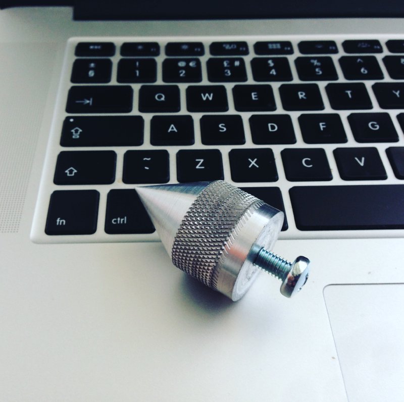
Whilst I won’t be using this on the current crop of guitars, it does give me ideas for how I might be able to fabricate parts for future things.