How to level a CNC router sacrificial bed with Fusion 360
Published 27 Jul 2018
I’m now one of the maintainers of the CNC Router at the Cambridge Makespace community workshop, and one of my first tasks as maintainer has been to replace the sacrificial bed that is mounted on the CNC router.
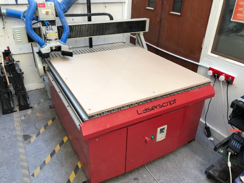
The sacrificial bed is the large wood base that is permanently mounted on the router to which work pieces are then in turn mounted (which is nice and fresh in the above picture, taken after I’d replaced it). Although in theory you can mount things to the metal bed on the router, for the majority of jobs done in a space like ours (particularly given our machine is only rated for wood and plastic work) a sacrificial bed which things can be screwed to readily simplifies machine use somewhat.
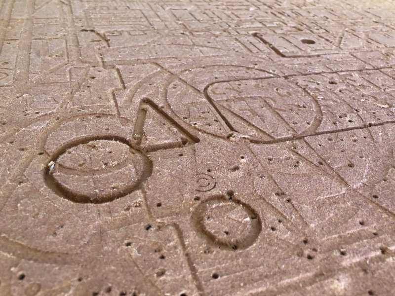
The downside is that over time the sacrificial bed is worn away by people screwing things into it and cutting through into the bed. At which point you face an interesting challenge - how do you make a new bed that is by definition exactly the size of the working area of the machine? It turns out that doing this in Fusion 360 required some non-obvious trickery, so I thought I’d write it up. This is what a well loved sacrificial bed ends up looking like:
The first thing I did when I started this task was look for existing design files that I could re-use. Unfortunately they seemed to have been lost over the course of previous CNC router owners coming and going, so I had to make my own. Thus I broke out the callipers and fired up Fusion 360 and recreated the bits of the CNC router I cared about: The metal base onto which the sacrificial bed is mounted, plus a model of the existing sacrificial bed layout wrt screw holes for mounting etc.
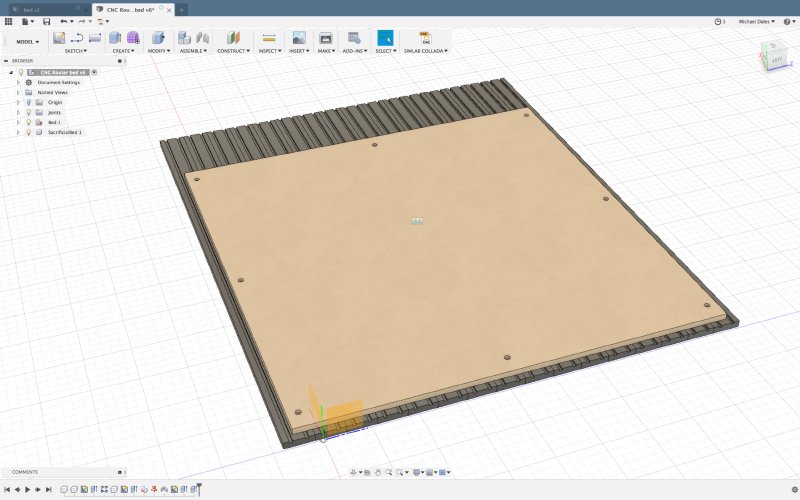
The bed is made from 16 metal extrusions, which are nicely symmetrical, but with the notable feature that there is no center slot, so the two middle screw holes have to be staggered either side. But that aside it’s a fairly simple thing to model. To try and and save the next person having to recreate the design yet again, I shared this design with the Makespace community - a nice upside to Fusion 360’s cloud based nature.
Having made the model, the next step was to make the CNC router make the new sacrificial bed. This is done in two parts:
- Firstly, we mount the new bed on the old bed and make the counter sunk screw holes to let us mount the new sacrificial bed on the metal base
- Secondly, we then face off the new sacrificial bed to make sure it’s completely flat
For those not familiar with the term, facing off just means making sure the material is absolutely flat, so we mill down the surface to remove any variation due to imperfections in the material or the base its mounted on.
The first stage was easy enough. Although the sacrificial bed is quite large, the mount holes are by nature within the area of movement for the CNC router. Thus I simply screwed the new bed onto the old sacrificial bed, cut the mount holes, and then was able to quickly swap the old sacrificial bed out for the new one.
The second stage though proved quite problematic: here we need to go edge to edge on the new sacrificial bed and the material size is actually 20 mm bigger than the movement size of the CNC router. This is okay, as I have a 1 inch (25.4 mm) wide router bit for levelling jobs like this, so the movement of the machine head plus the diameter of my router bit means in theory we can face off the new sacrificial bed without problem. The problem however is trying to get the software side of things to understand those constraints. I spent a good 90 minutes with both Fusion 360 and Vectric VCarve Pro trying to find an elegant way to express what I wanted to do with no joy. The fundamental problem is that neither bit of software understands the constraints of the machine you’re using, just the constraints of the material.
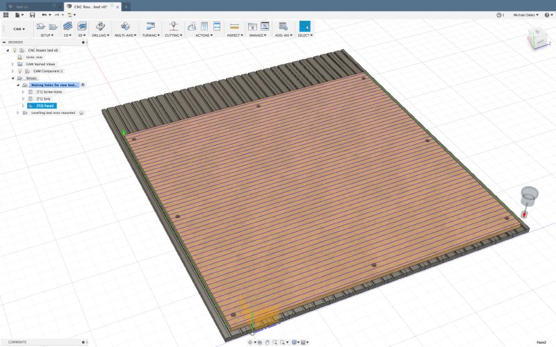
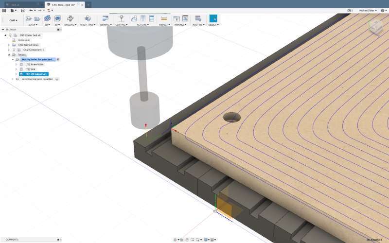
Look at the above picture as an example: here I’ve told Fusion 360 that I want to face off the sacrificial bed using my 1 inch router bit. You can see that it’s made this nice pattern that relies on going off the side of the material and back in again. I can’t do that in this case as I’m at the limit of my machine’s bed here: there’s no room in which to execute that turn, and I failed to find a way to express that constraint to Fusion 360 in any of the options.
I tried some other tool path generation techniques in Fusion, for example using its adaptive clearing method to just say make the surface of the material match the model, which should be equivalent to facing off here. Here I hit another issue with Fusion 360, in that it still wants to enter the material from the side. Even if I try explicitly telling Fusion I do want’t to have a lead in, it still has some partial path coming in from the side.
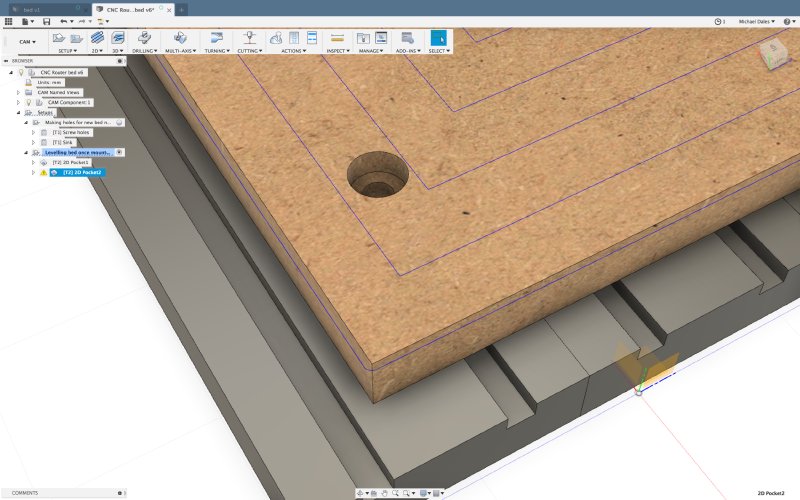
After much fiddling, I managed to stumble across a solution. I reasoned that if the sacrificial bed was treated like a pocket, then surely it’d not execute a lead in manoeuvre, as in pockets you’d normally hit a wall doing so. Thus I set my piece origin to the center of the material rather than a corner as I’d normally do, and used the 2D pocket path, and indeed there was no lead in issue, but it still insisted on going outside the material at first:
Because there are no walls on the edge of this pocket, Fusion 360 reasonably assumed it could do that. In the end I realised that I could control the step over amount for the spiral shape it is making, and by playing with that number to make it create a slightly tighter spiral I managed to get a tool path that remained within the material near perfectly.
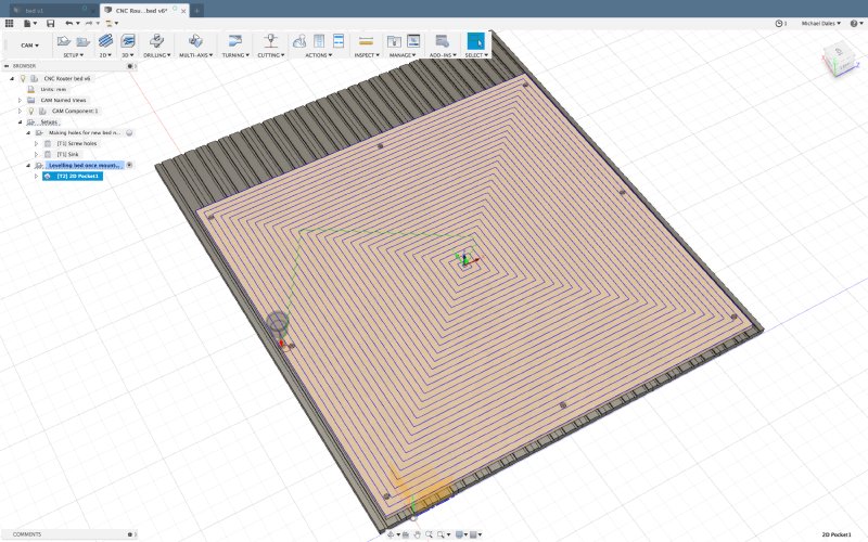
Thus I was able to execute this as my face off pattern and I got the nice finished sacrificial bed you see in the opening picture of this post.
Ultimately the problem here was that I couldn’t find any way to teach Fusion 360 about my machine limits (and it’s not alone in this issue, it’s just that I happen to use Fusion 360, I hit similar issues in my brief play with VCarve Pro to see if it was more sensible). I was getting to the stage where the irrational part of my brain was going to write some software to generate a bed levelling pattern based on machine limits rather than material limits - and the whole point of getting into woodwork was as an escape from writing software!
The other frustration with this kind of problem is that it’s not until you try run your tool path on the CNC router that you have any sense of whether it’ll work or not: do you get the dreaded “x-axis out of range!” message or not. I did manage to work out that using a combination of ncviewer.com to visualise my tool paths and reading the low level g-code I could take a good stab at whether a design would work or not, but reading g-code is not for the fainthearted, and ultimately the whole process was a user experience nightmare for what should have been a simple enough task.