A fortnight out the shop
Published 1 Dec 2020
Another slow fortnight, due to a combination of urgent client work and a bit of ill health. But I’ve used this down time to try and get myself set up for when I do get back into the workshop. So lets have a look at some of that.
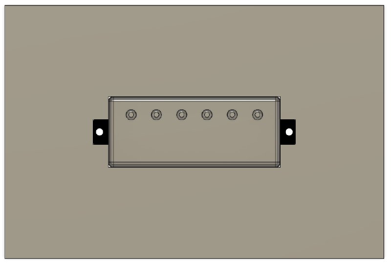
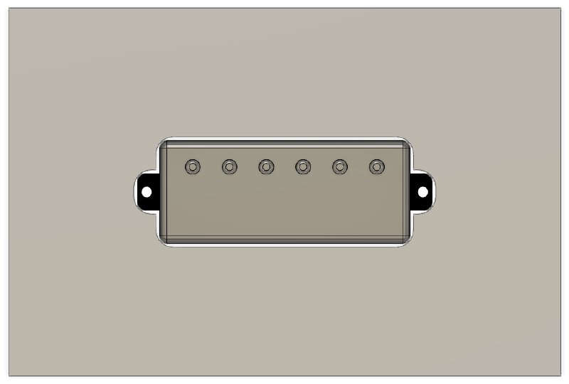
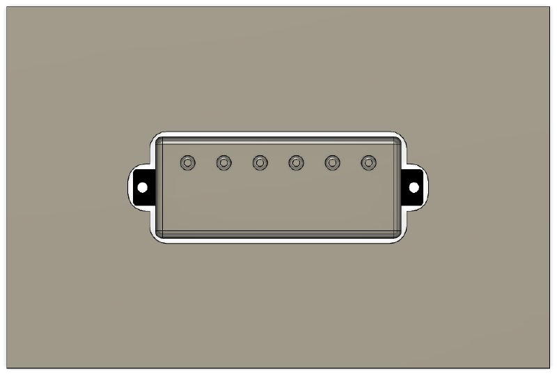
The pickups for the two guitars I’m currently working on have arrived from House of Tone, which is exciting:
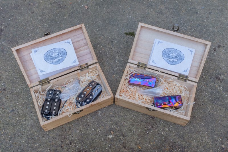
I’d forgotten that I specified burnt chrome for the mini-humbuckers, so that was a fun surprise when I opened the box :) The look lovely, Matthew’s really done a good job on them.
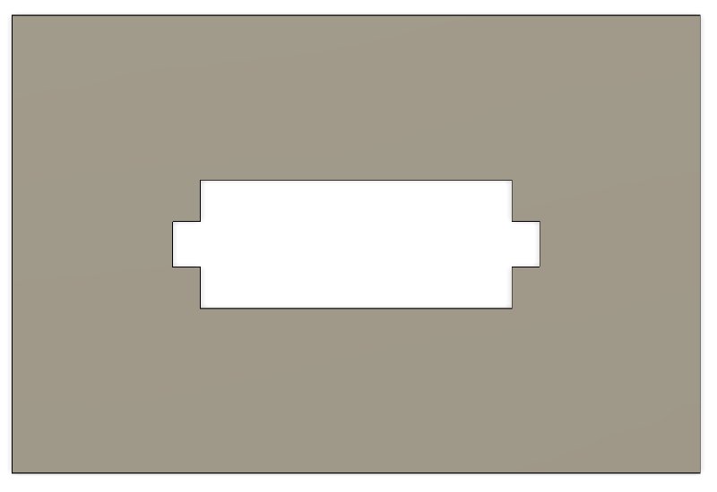
Before I can install the pickups there’s the little issue of making holes for them to sit in, aka the pickup cavities. In the past, I’ve been building guitars that mount the pickups into the pick-guard or bridge, so I can make the cavities quite large to make alignment easier and potentially allow them to be swapped for a different style of pickup later. For example, here’s a picture of the Green Tiger’s pickup cavities:
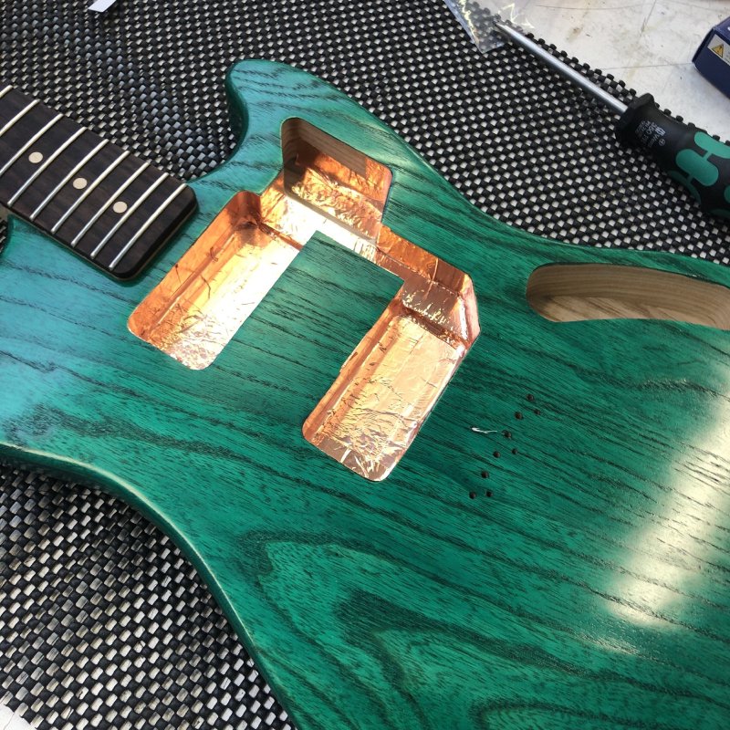
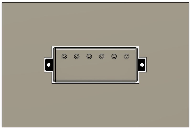
However in the two guitars I’m building currently I want to do away with the pick-guard: partly to show off the wood better, and partly as I dislike having to remove the strings to work on the electronics so everything is going to be accessed from the back of the guitar. To mount the pickups I’ll use small ring mounts, similar to what you see on Gibson style guitars:
This does mean however that the hole for the pickups will need to be much more snug so as to fit behind the mount ring whilst still having enough room for the pickup to fit. For this reason I’d been putting off making templates for these guitars until I had the actual pickups in hand to measure, as I find although the sizes are roughly the same each manufacturer has slight differences. Now that I’ve got them, I was able to design the templates.
The first thing I did was go back to my Fusion 360 models for the guitars and properly input the pickups, which at this point had just been roughly positioned. In fact my guitar CAD designs tend to have many different pickups in the model, most of which are hidden, to let me see what the guitar would look like with different pickup options. But for these guitars was time to just have one set of pickups and tie down all the specifics. It was at this point I realised I had a new challenge I’d not anticipated, and I thought I’d walk you through this.
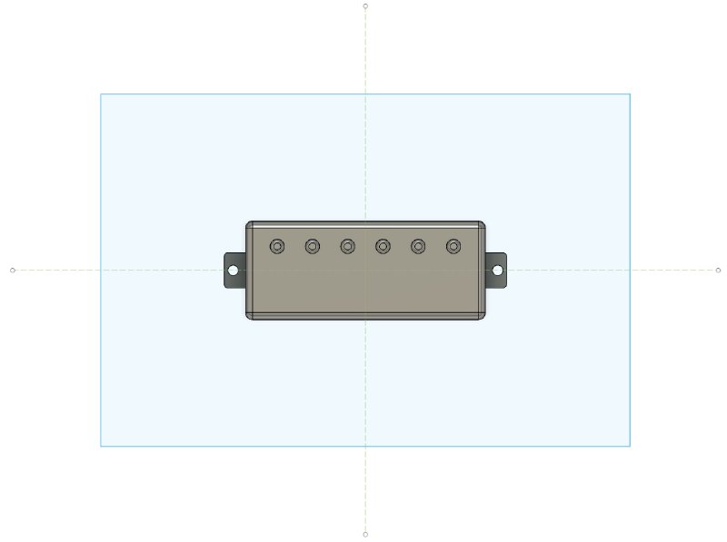
So, let’s start with just the pickup, in plan:
So, we can create a minimal shape that will be our template for this by removing the space where the pickup would be based on the outline:
And we can see that the pickup fits snuggly:
However, this is clearly a bit non-practical so far: we’ll need some wiggle room around it, so let’s add a millimetre on all sides:
That’s a better template shape, but I can’t actually make a hole in the guitar this shape from the template, as I can’t make those right angle internal corners; at least, not practically - perhaps if I spent a lot of time with chisels I could. But I plan on using an hand-router to make this hole, and the hand-router has a round bit, so if I cut this template as is I end up with a hole like this:
That’s no good - the pickup doesn’t actually fit!
The above assumes I’m using my regular 12.5 mm follow bit, which is what I normally using when routing out things using a template (for example, it’s what I used when routing the cavities on the green guitar in the earlier picture). You can get a smaller diameter bit, but unfortunately in terms of robust router bits with a follow bearing, the smallest you can get from a lot of places is 9.5 mm in diameter. Whilst you can get smaller, and indeed I have a 6.35 mm follow bit I use when making the cavity for the truss-rod on the neck, those bits are not that robust and not really suitable for this job. So let’s see if the smaller 9.5mm will solve our problem:
Almost, but not quite: I still have to add a bit more room. Let’s take that initial 1 mm offset and make it 1.5 mm:
Chicken dinners all round: we have a winner. Now, this may seem somewhat obvious, but it’s a detail I’d not really thought about because in my past builds I’d either not needed to be so precise or I’d used a CNC router where I could use a smaller diameter bit and get away with it (it’s having a robust bearing that’s the issue). This is the danger of CAD at times - you can design what you want, but that doesn’t mean you can necessarily make it.
You can see why I’m concerned with the margins here when I place the pickup mount ring on the design:
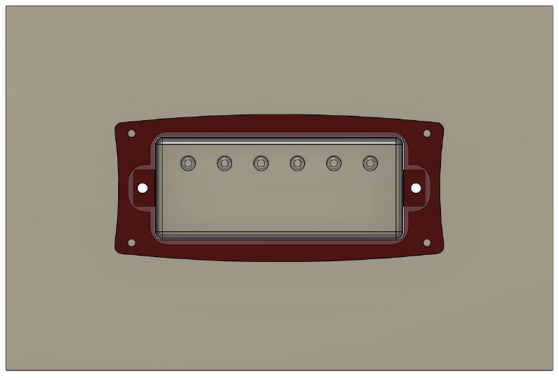
I need all the cavity to be kept tidily under that mount ring. As it happens, my design has enough play in it that I can afford to give myself a bit of wiggle room and expand that up to a 2 mm offset comfortably.
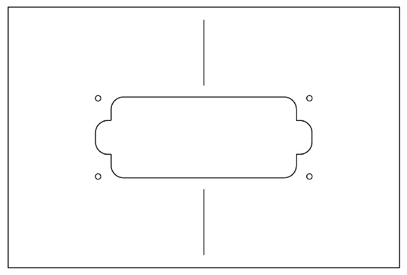
That done, I can finally make the vector design that that I’ll laser cut to make a template - I’ve just added on the mount holes for the pickup ring (which will also help secure the template for routing) and I added a couple of lines to let me line up the template on the guitar body:
So my plan this week (depending on some post turning up, as detailed below) is to get that template made (and another one for the full sized humbuckers for the other guitar) and then get to cutting the cavities.
As an aside, making the pictures for this in Fusion 360 was a real pain until I changed how I approach things like this.
Initially I kept tweaking the offset and corner radiuses in the sketch, which is where I normally would do offsets and such, as I want to turn that sketch into the vector file I’ll send to the laser cutter. But Fusion 360’s parameteric design flexibility doesn’t really extend to sketches, so I’d have to keep manually deleting and redrawing things every time I changed the offset or bit size, and it was driving me mad.
However, I realised that if I changed my workflow so that I had an initial sketch with just the pickup outline, and then I added the offset and radius in the 3D model of the template rather than having them in the sketch then these things appear in the history timeline and will update automatically as I adjust the offset and radius parameters - it was so much easier that way. Then once happy everything was in the right place I created a new sketch from a projection of the top face of the template’s 3D model and bam I’m done and everything will just update nicely if I have to tweak it later.
I guess the moral here is if you feel like you’re fighting Fusion 360, you probably are and there’s a better way there, you just need to find it.
The other bit (pun warning) of prep work I did was buy some… bits. I bought myself the aforementioned 9.5 mm router bit with follow bearing, but I also got myself a good bit for counter sinking holes and a low profile bearing bit for cutting that neck pocket issue I hit the other week.
The counter sinking drill bit is a Hall’s Hexibit countersink, which I’ve used many a time in the Makespace workshop, and always gives a nice clean finish, unlike some others I’ve used which can tear the wood. It’s not cheap, but in terms of finish it seems reasonable. It’s also a testament to my habit of photographing everything that I was able to work out who made the bit and which model it was by looking on my phone rather than having to go back into the workshop. Yay for compulsive documenting of everything with phone pictures.
The low profile bearing bit for the neck I failed to find on Trend Direct, where I normally get my bits, and after finding one on a US site but not wanting to wait several weeks and pay a lot for shipping, I found one on Amazon. I try to not use amazon when I can support a supplier directly, but needs must occasionally. However I then later discovered (after I ordered my 9.5 mm follow bit) that Trend *do* make a low profile bit to suit my needs, just I didn’t know the magic set of terms to find it - sigh. Still, I should be set once all these turn up to get cutting.