A week out the shop
7 Sep 2020
This last week I didn’t make it into the workshop unfortunately, as contract work needed to be put in order and IT admin issues caused me to spend time I’d otherwise spend in the workshop keeping the digital lights on. But I made some progress in CAD on the current guitar build, and learned something new, so I might as well share that.
A few weeks ago I posted a picture of the guitar I’m currently building as a way of shaking down my process in the new workshop:
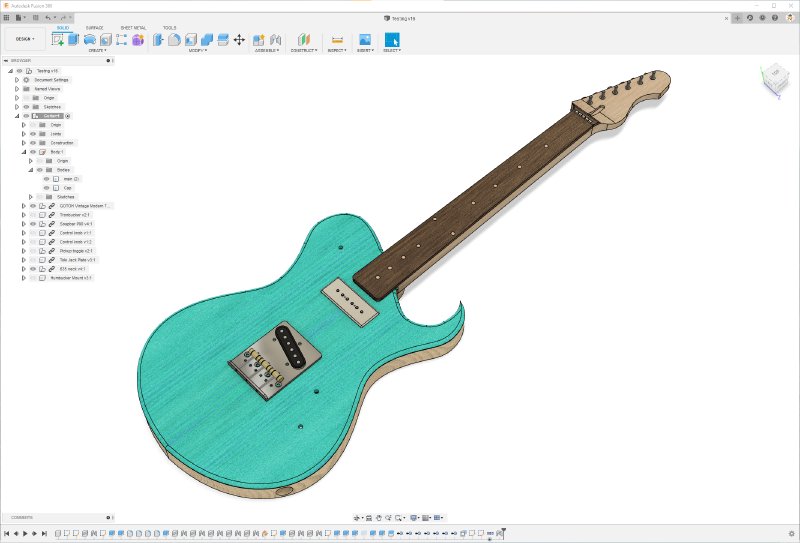
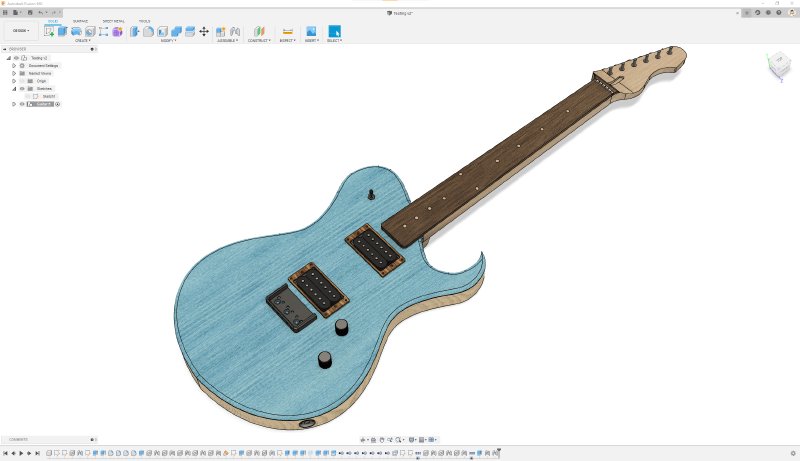
However, whilst I like tele-style bridges, they’re not to everyone’s tastes, so I decided to do a bit of a more traditional layout for this guitar, switching it up to two hum-buckers and a short hard-tail bridge, making it have a bit more mainstream appeal as I’d like to move it on once finished:
In doing this I filled in some of the detail missing from the original model, adding both the holes for the pickups, and the pickup mount rings needed to hold the pickups in place. This presented an interesting challenge that I’d not had to solve before in Fusion 360: how do you joint together two rectangular holes?
In Fusion 360 jointing is the way you take two components of your design and join them together such that Fusion 360 will keep them stuck together as you make other changes to your design. An obvious example of this in a guitar is I’ll joint the neck to the body: I tell fusion that the neck joints the body in the neck pocket, and then no matter what I change in the guitar body, the neck will always stay in the right place (assuming I don’t remove the neck pocket itself).
To do this you need to pick a point on each part to match together. Normally when jointing things in Fusion 360 you select an anchor point on one of the faces:
You can see that fusion is offering me nine anchor points on this rectangular face (one in each corner, one in the middle of each edge, and one in the middle that I have selected). Once I select one here, I’ll select a similar anchor point on the other side, and bam, these things are stuck together.
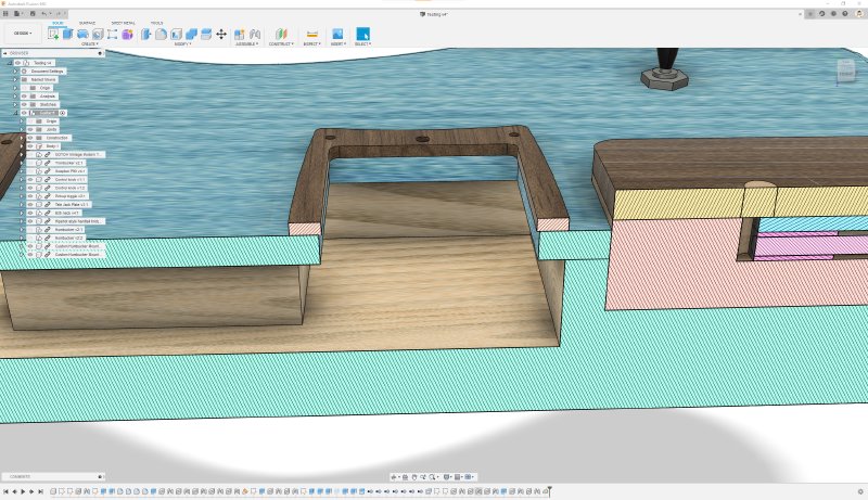
But in my guitar I want to align the hole of the pickup mount with the hole in the face of the guitar, so there’s no face for me to click on. If I remove the pickups the issues is more obvious:
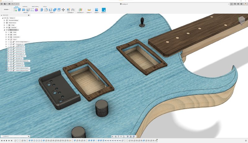
If the two holes were exactly the same size I could click on the lines at the edges of the hole and match them up, but one is slightly bigger than the other to ensure you don’t see the inner lip protruding. Again, a bit more obvious in a sectional view: you can see the mounting ring has a slightly narrower aperture than the hole in the body cap.
If the pickup hole was round, then this wouldn’t be a problem: Fusion 360 will automatically select the centre of a round hole if you hover the mouse over the edge - presumably as there’s no obvious place to put anchor points on the edge itself. But with rectangular holes you don’t get to select the middle of the gap.
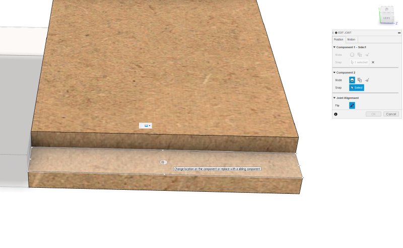
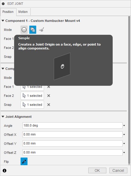
After a bunch of searching, I finally found the solution in this video on the Fusion 360 forums. If you look at the jointing dialog, by default it is in simple mode, where you just select the anchor points as I described above:
But there’s two other modes. The second mode is called “between two faces”, and is exactly what I want.
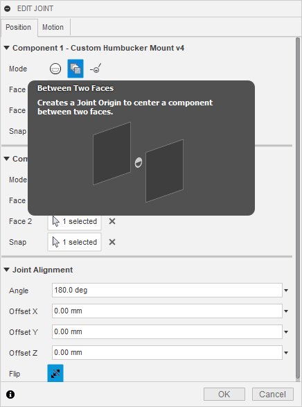
In this mode I can specify two faces, one either side of my rectangular hole, and then it’ll let me draw a virtual line between the two faces based on a common anchor point, and then give me a joint point in the middle of that line. Sounds a bit complicated, and I guess it is a bit, but it’s exactly what I need. It’s hard to show in pictures, but the video I linked to above is very short and shows you how it works.
Whilst my use case here is a bit esoteric, this same technique is useful if your designing something where you have a rectangular slot you want to fit another part into, say if you’re designing furniture.
Just for completeness, the third jointing mode lets you pick two edges on your design and create a joining point where those two lines intersect - really useful if you have rounded corners on your design but need a reference point where the sharp edge would otherwise be.
The other thing to note from the above is I designed my own rounded pickup mounts (the first picture has the original, more traditional, straight edged design, the next ones have the more rounded design I settled on). I wanted a more organic shape than the hard lines you get on those normally, and so designed these ones that bow in on one axis and bow out on the other.
Normally these could come in plastic or metal, and here I’ve modelled them in wood, and I’ll have to see how that looks in practice. As a guitar builder there’s a terrible temptation to do everything in wood because that’s the main medium you’re used to working with on guitars, but I really don’t like a guitar that has a uniform wooded appearance to it personally; I definitely like the juxtaposition of different materials on guitars - woods, plastic and metal. But the cost of making a couple of these to see is low, and if I don’t like them then I can make them with laser cut acrylic or 3D print them easily enough.
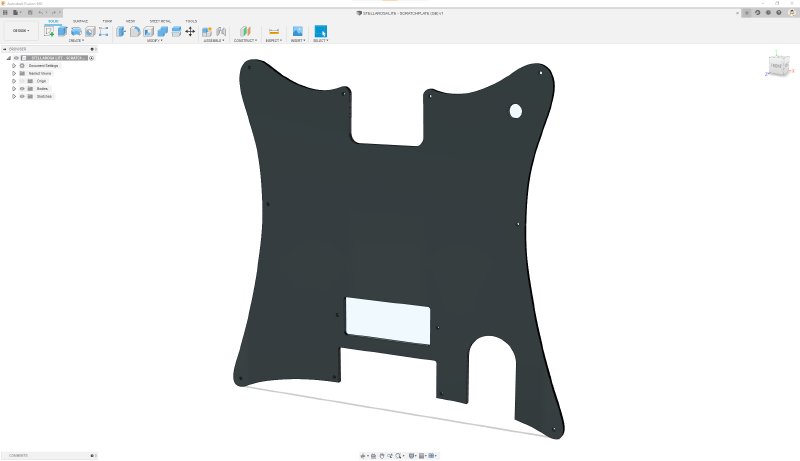
I spent a bunch of time doing an increasingly silly workflow to help me get to a point where I can laser cut some pick-guards for my workshop mate Fidelity Guitars. Matt normally will CNC route his pick-guards, and on some materials like ABS or PVC plastics that’s the right thing to do. But it’s quite slow, and a bunch of his pick-guards are acrylic, so I offered to laser-cut them. Not only is this quicker to cut this way, but you get a nicer edge on acrylic this way that needs a much less finishing work to make good.
Matt’s designs are in Turbo CAD, and when we last tried to do this at the start of the year it turned out that the SVGs Turbo CAD exports turn the curves into a set lines with very few points on them, so those nice circles come out line hexagons etc. In the end we had to export them as STEP files, import them into Fusion 360, and use the excellent DXF 4 Laser plugin to export them as DXF that’s compatible with the laser cutter.
Unfortunately this time that workflow didn’t work. The STEP files are still using lines rather than curves, but there’s just a lot of them so it looks to the eye like a curve. Unfortunately there’s so many than DXF 4 Laser took too long to complete and Fusion crashed out as a result. In the end I just created a sketch from the front face in Fusion 360, exported a DXF from that, and then ran that DXF file through Adobe Illustrator to make it compatible with the Laser Cut 5.3 software used at Makespace on their laser cutters.
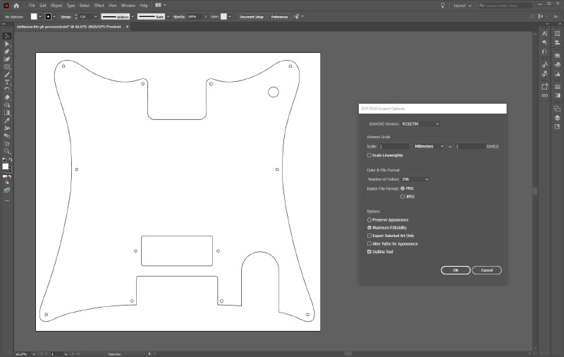
Laser Cut is notoriously picky about which particular subset of DXF it’ll work with, which is why I like the DXF 4 Laser plugin as it normally sorts this all out. However, if you do have a vector file you need to clean up, then using Adobe Illustrator you can export it as DXF version R13 and it’ll generally work. You will need to ensure there’s no groups in your design, it has to be totally flattened in Illustrator first, and you convert any text to strokes. Also when importing and exporting ensure you have 1 mm = 1mm as the scale at both sides to prevent sizing issues. As ever, a hat tip to game-maker extraordinaire Katy Marshall for teaching me all this voodoo.
After this batch are done (I’ve already done all the processing for this set of pick-guards) I’m going to see if I can play with Matt’s Turbo CAD setup and work out if there’s a better interchange format we can use between Turbo CAD and Laser Cut that doesn’t require all these hops.,
So a very software heavy week. Hopefully more dust making in the near future!