A week in the shop
Published 15 May 2022
Tags: älgen, delfinen, fusion 360, jigs, laser-cutting, templates
This last week in the shop has been really quite productive, and enjoyable, in a way that’s been absent for a little while. Over the last few weeks I tried (once again) to change how I workshop, and I feel I’ve found a productive place, at least for the short term. It’s a combination of how I schedule my workshop time, adjusting my building plans, and even something as simple as getting a comfortable workbench stool so I don’t feel the need to head home to do CAD or other admin work.
All these changes seem to have come together to help me find a productive groove this last week. The main improvement is that when I get stuck on one thing in the workshop I have the time and space to switch to other tasks and to iterate on problems without them hanging around for a full week before nudging them forward.
We’ll see how it evolves over the coming months as my day-job work demands ebb and flow, but for now I’ve been really enjoying this last week; there’s been a fair share of setbacks, but I’ve been able to deal with them much more effectively and it’s been fun in a way that guitar building hasn’t been for a while.
So, with all that said, let’s take a look at these setbacks and how I iterated my way around them :)
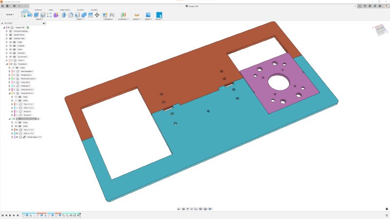
Last week I wrote about designing a new template to let me cut the slots for mounting the 3D printed guitar body. We finished up with a design looking like this:
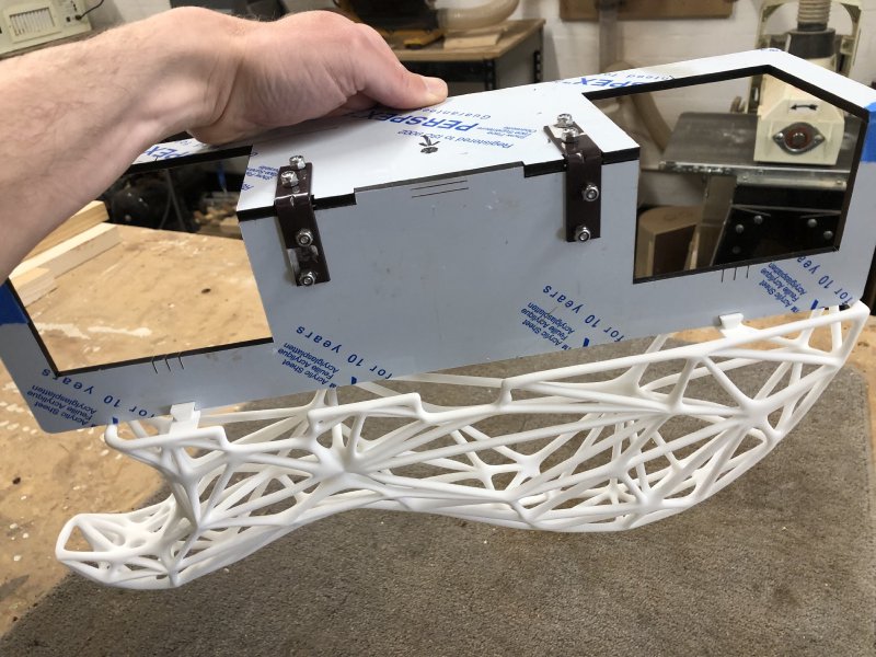
The week started with a quick trip to the laser cutter at Makespace, and I cut out both the parts for the new jig and a revised neck template for the other guitar I’m building (more on both that other guitar and the template revisions later):

After a brief trip to the drill-press to countersink the holes for the screws to mount the brackets, I had the new jig assembled and ready to go. Here you can see it in place, but note the channels cut here were made with the old template that didn’t work - I was just checking it for fit at this point.
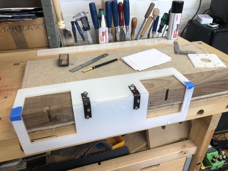
The angle brackets I got from the hardware store are not perfectly square, but it all goes together well enough.
This design, being an iteration of the previous, chonkier MDF version, uses the same mount screw to attach the jig to the guitar body; the screw goes into the material that will be later removed for the neck pickup, so it’s one of the few places I can put a screw in like this.
You can see the hole for the screw in the above in the middle of the bottom bit (and that I’d yet to countersink that bit - doh). But there’s no screw there yet because the last attempt to use the jig had an alignment issue and I needed to move the screw hole that I made last time about a millimetre to the right. Thankfully moving a screw hole is a technique that I’m now well used to: out comes the cocktail sticks and wood glue!
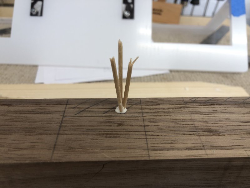
For all my fancy modern laser cutting and CAD, I still need to plug holes like any woodworker :) And an hour or two later we’re ready to start again:
Unfortunately this is where our old friend, measure, measure, cut reared its ugly head…
Working in the analogue world, I’ve learned to be more reactive in my engineering than I am in the digital world. In general in woodwork you find things are never perfectly precise: the wood will change size, the grain of the wood will deflect your drill bit minutely, or there will be a defect to be worked around in the material. In the digital realm you have the luxury of making things near perfect, but in the analogue world you need to go with what’s there often.
In guitar design there’s a tension that comes from my designing the guitars in the digital world first and then executing that design in the analogue. I’ve learned to spot these over time, but I didn’t think to apply it to my 3D printed parts, as they feel to my like digital world components: designed on and built by computers for me, out of uniform vats of material dust, precisely fused by everyone’s favourite technology:

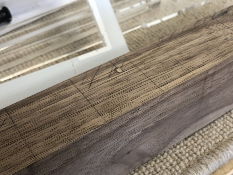
But alas, 3D prints are analogue parts, and just like wood after it’s been cut out, they have a tendency to shrink slightly after printing. In my design the mounting posts for the guitar wings were 280mm apart, and so I’d designed my jig from that exact reference in the same CAD model, so my channels in the wood were 280mm apart. I never thought to measure the 3D print to check how big it actually was. Well, not until I’d taken a second go at finishing the failed channels and the realising the 3D print wouldn’t fit on the body. Measuing the left hand edges of the mounts we can see:
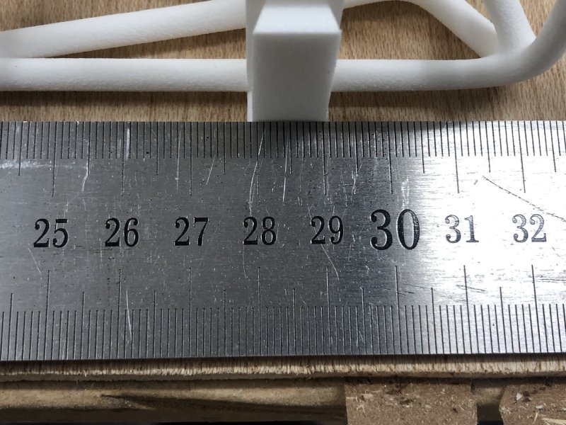
279 and a bit millimetres, not 280. 🤦♀️
I feel a bit silly that this never occurred to me until this late stage: I know that 3D prints can suffer shrinkage: my time using Ultimaker 3D printers at Makespace had shown me that 3D prints needed (as a crude approximation) to be scaled up to 103% on those particular printers using PLA.
But my smaller test print with Shapeways for these mounts had been spot on, and I just assumed from that that Shapeways had dialed out any shrinkage with the parts. And to be fair, this is 0.3% shrinkage, much less than we saw with the Ultimakers. But it’s enough to cause two unforgiving parts not to fit together!
So, time for yet another jig revision!
Back to Fusion, and I tweaked my jig once more, and added another couple of features to it based on the brief time using the above version. When I started out I hated making jigs, as it was time designing and making something other than the thing I wanted to be designing and making; now I still don’t love it, but I have a much better appreciation to the design effort that goes into a good jig:
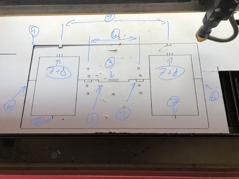
Take this one, now on its third iteration, has a bunch of little features beyond the primary design goal of being a guide for a router:
- Stepped edge to force alignment of two parts
- Cut out step to allow for rounding of angle brackets
- Depth markers for the router bits for the two cuts, set from the edge
- The angle brackets are spaced to let me place the base between them so I can use the depth markers
- All corners are rounded - I’m done cutting myself on laser cut acrylic because computers like sharp corners!
- This edge is designed to align with the end of the guitar body
- A centerline reference
- Guide lines that let me ensure the second side is matched perfectly with the first
- Key to check that template mates with 3D part before I cut!
So designing a good jig takes a lot of consideration, and it’s worth taking time over if you’ll be using them often.
That last one was the primary lesson here. Whilst in theory I could try make an adjustable jig that lets me set the width to match a give 3D printed part, at the low volumes I have currently it’s enough just to have a couple of jigs, but I need a way to ensure that the one I’m about to use matches the 3D print to hand, so with this I can just put the 3D print in the slot to check.
As you can see, after I laser cut my next iteration, we had a match!
So, a week on and I’m slightly further along than I was last week, in that now I have a jig that is cut and is the right size, but I’ve still not yet fitted the 3D printed part! On one hand that is frustrating, but I’ve been able to solve some issues and improve on things along the way, so I’m actually quite happy with the progress. I don’t mind dealing with issues so long as I can keep the momentum up, and being able to do that here has helped. Moving to a laser cut rather than a CNC routed jig was a key part of that, as the time and effort required to make a new version is so much lower, and it goes from being a labour to just a thing you do without thinking.
I mentioned at the end of the last notes that I was starting a new Corvette build. This is my first own fully designed guitar, and I completed a left handed version last year that is now with its owner, and I felt I should have another more guitar to have for shows that was more conventional, and also something I’d already built before. Part of the reason for the stucato progress on the Älgen build is because I’m building an entirely new process as I go, so to fill those gaps I wanted to make a guitar where I’m just doing the building (for the most part…).
My friend Adan pushed me a little on this: why build a more conventional guitar when I can’t please everyone: don’t I just risk spreading myself a little thin? He even kindly made me one of his MakerQuotes plaques to that effect, which now sits on my bench reminding me of the limits of how I scale:
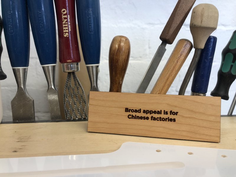
The conversation has played on my mind all week, and has helped me refine in my head what it is I’m building and why: I questioned what it is about my guitars that make them my guitars. I’m not sure if it was Adan’s intent to send me on a deep bout of soul searching, but it was very useful, and for that I’m grateful he did.
I was reminded of a comment I got from the person who commissioned The Green Tiger build: they liked the little details on my earlier builds where I had 3D printed the controls knobs, and they were keen to have the same for their build. It was a small detail in the scheme of things on a guitar build, but when you’re ordering a custom guitar just for you, all those details matter.
With the original Corvette build I didn’t 3D print any parts, but I did make custom pickup rings and in the end made my own bridge plate too, so there’s a similar core of custom-made details in there that aren’t obvious at first glance that made it a unique instrument. And I think that then is the common like between the two guitars I’m building: although one is more obviously so than the other, both will be built using a hybrid of modern digital fabrication (laser cutting, 3D printing) pushed up against traditional hand building techniques (hand planes, saws, etc.). That then is what I think a Michael Dales built guitar is, and I need to ensure that each build pushes that intersection of techniques.
I already had thicknessed the wood for the new Corvette build a few weeks ago: we’re starting with a swamp-ash body and a maple neck (that will eventually get a rosewood or wenge fretboard, depending on what I have in stock). It’s a two-part body blank, so the first task was to get the centre edges planed true for gluing. I started getting it roughly true using the planar machine in the workshop, and then getting it properly true by hand:
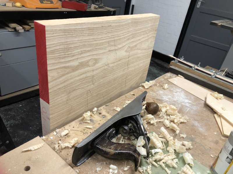
Planing things by hand is both increadibly frustrating to get right, but also increadibly satisfying when you do get there. With everything true, it was time for glue and sash clamps:
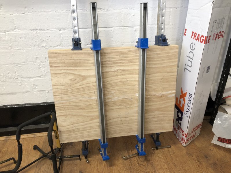
And a day later I have my body blank ready to go. Well, almost: the joint won’t be perfectly at 90 degrees, no matter how good my hand-plane game is, and also sash clamps don’t make it easy to get the edges perfectly lined up, so I need to true off the blank now that it’s become one. In the past I did this by running it through the thicknesser again, but there’s now a sanding thicknesser in the workshop which is much better for taking wood down that final step without the risk of tear out:
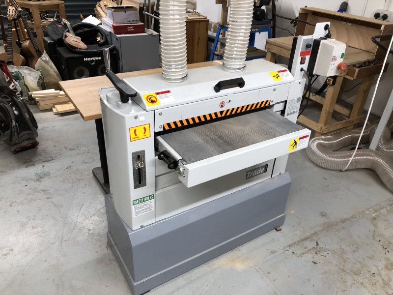
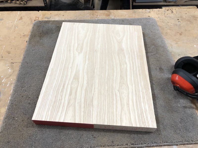
A few passes through that and I have a perfectly levelled blank ready to go:
The next stage is to use a template to cut out the shapes for both the neck and the body. You saw earlier on in this post that I had made a new version of my neck template: this is also my third iteration of this template. Here you can see the first and last versions:
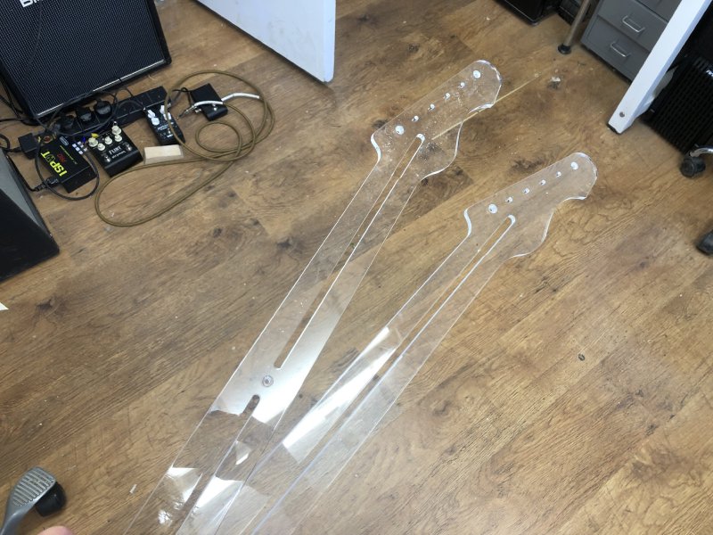
Photographing clear acrylic is awkward, but hopefully you can see the difference is that extra chunk of material in the truss-rod channel you can see in the middle of the one on the left (the new one). The first version had too much flex in it, which I had to fight using double sided tape. In the second version I put a narrow bridge of material in the middle, but I still got flex there, so now I have much more material and a screw to hold it in place: this has totally eliminated the flex!
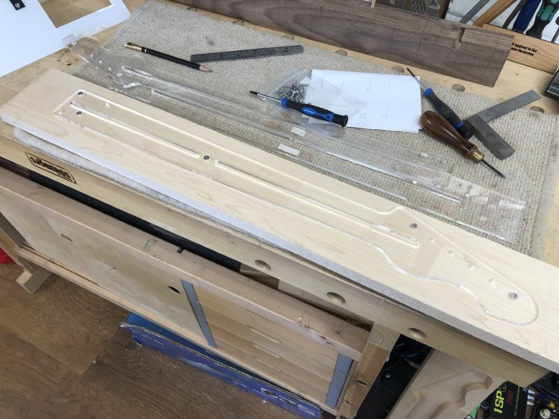
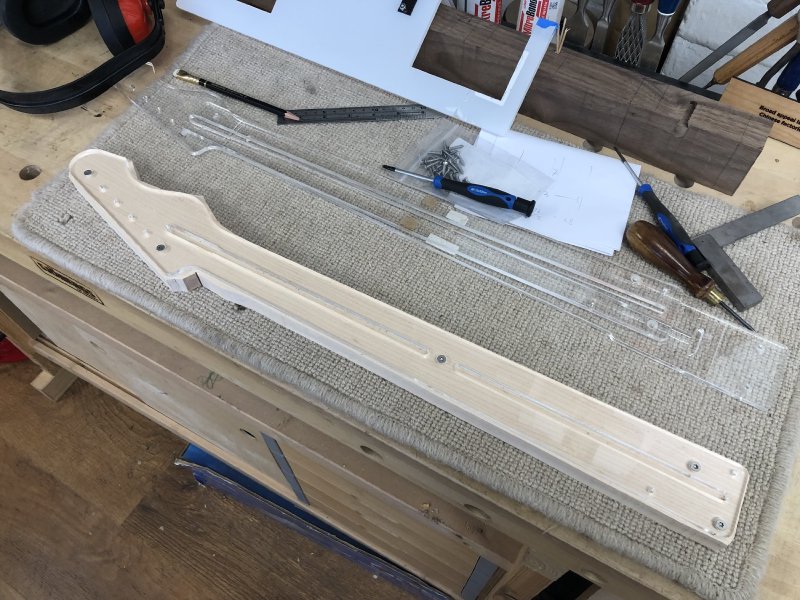
The next stages should be tried and tested, given this is my twelth build, but you know me better than that by now, so obviously something different is going to happen this time around. The first stage was the usual: get the template on the neck blank:
and trim off as much as possible with the bandsaw:
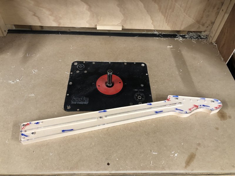
But whereas normally I’d use a hand-router for trimming the wood flush to the template, the workshop now has a dedicated table router, so it was on to that:
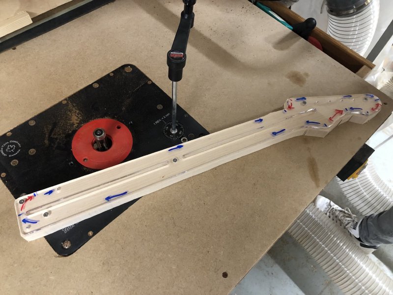
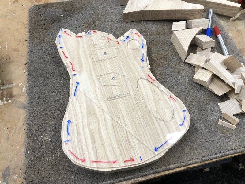
The mix of blue and red arrows you see are direction cutting indicators for me. With a router you always want to work against the spin of the blade, otherwise there’s a risk of your workpiece flying off. With a hand-router, and using a bit with a guide bearing at the top of the bit, this meant I’d work around the wood in a counter-clockwise direction. The problem with this is that this means you’re working against the grain of the wood in places, which leads to tear out, which leans to Michael spending a lot of time sanding.
With the table-router here it has a guide bit on the top and the bottom of the blade, so I have the option of flipping the workpiece over to ensure that I’m both always working against the direction of the bit and working down the grain. So here blue is where cut with the template on top, and red is where I cut with the the piece flipped over.
The result was the cleanest template cut I’ve ever had.
In theory I could have done similar with a hand-router, but hand-routing a neck, dealing with the cable, knowing how far I am from the template when it’s fixed upside down on the bench, really appealed less than the sanding did.
Next up on the table-router was the body, but for that things didn’t go so well, and I only have myself to blame. Here we have the body at the post bandsaw stage before I introduced it to the table-router:
The thing to note here is how there’s still wood around where the horns are to the top - I didn’t managed to trim it as close as I did on the other edges.
This wasn’t abnormal, usually I get as much as I can out of there, but then just accept that it’ll be several slow passes with the hand-router to work my way down to the template. A router of any sort is a finishing tool, not a roughing tool, so you only want to take a millimetre or so off at a time, and thus here I’ll just have to slowly work down to the template.
Unfortunately, whilst I was doing this on the table-router I created a sort of dip for me to work in, and as I was working one side of the V made by the horn and the neck pocket I caught the other side, which whipped the body in an unexpected direction. Thankfully I had two hands securely on the material and both were well away from the danger zone, so it was just a jolt rather than something flying across the room, but it was enough to give me a bit of a surprise and to ruin my plans for the body. All on the final bit too: I’d already done all the sides nice and flush, and the horns were teh final stage.
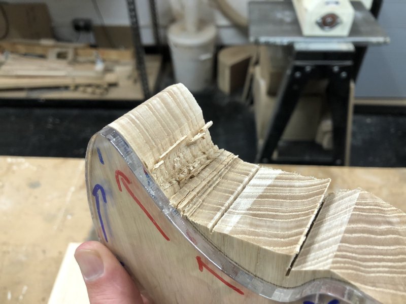
You can see that the material has been torn up under the template, and has done a good few millimetres.
At this point, after the surprise and disappointment, it was time to down tools and have a cup of tea whilst I recovered and then to figure out what I can do with next steps, and reflect on a nice reminder that routers, or all sorts, are angry little machines that need to be treated with great respect.
The fault is entirely mine: I should have worked harder to get more material out with the bandsaw. What was easy to control with a less powerful hand-router was more at risk with the more powerful table-router. I had left that extra material because the fence was blocking me getting in any more, but I could have removed the bandsaw fence and got those last bits out, but I didn’t want to have to re-calibrate the fence afterwards. A poor time saving optimisation that had worked in the past, but I should have re-calibrated my expectations for the new tool.
There were two options that presented themselves: I can either plug the gap (something I have done in the past, on which I did a little write up, though that was on a more regular defect caused by an errant CNC-router), or I could reshape the guitar to work around the defect. I’ve often pointed out to people that guitar body shapes are ultimately fungible: the only part of a guitar design that has to be as intended is the position of the frets, the bridge, and the nut, and you can do anything with the guitar body, and no one has to know what your original intent was unless you insist on blogging about it all the time… Perhaps now was the time to make good on my own advice.
After chatting to my follow workshop-mates about the options, I’ve opted to round it it out, and give it a slightly more squared off look. I first sketched this out on the guitar:
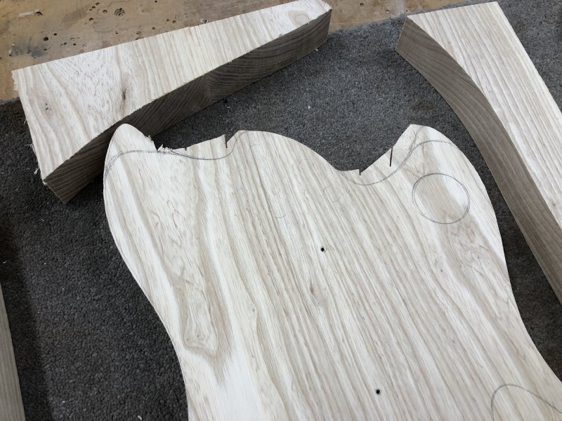
You can see the offcuts there which I retried just to see if I had matching wood for patching before I opted for reshaping things. Having measured the damage, I then went to my CAD model and worked out how it’d look overall:
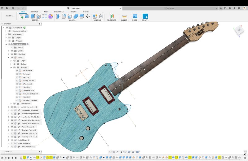
Here you can see where it would have been and where it’s going now. I have to say, I’m actually quite taken with the new look. It’s a bit Danelectro/Reverend/Frank Brothers, but also still its own shape.
It goes without saying that I’d definitely have rather not got to this point via this particular path, but I can say that the result is I’ve a design that I’m suddenly quite excited about executing. The original Corvette design was made with a specific customer in mind, with a more metal look, and I feel this new look is more me.
The other obvious advantage is that it’s a better design for clearing excess material away with a bandsaw, which is now a new metric on which I’ll be ranking guitar designs :)
I’ve spent the weekend refining this design and getting more excited about it - partly down to the new looks that are more me, and in part thinking how I plan to leverage my hybrid build focus on it - but that’ll have to be in next week’s notes: these notes have now gone on for quite a bit, so I’m going to wrap up here. I can really start to feel the time pressure on these two guitar builds, which I want to get significanly done on at least one by end of June. So time to ship these notes and get back to building!