A busy week in the shop
Published 16 Dec 2018
This week was fairly busy in the shop as I try wrap up two guitars, and had another one come back in briefly for a repair that turned into an upgrade.
The Clydesdale offset build has properly entered its assembly phase. This week I did the cavity EMF insulation, made a prototype pick guard, and finally fitted the neck to the body,.
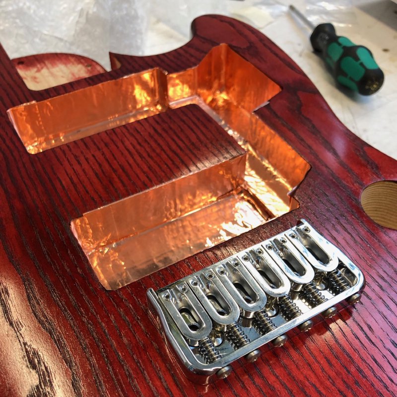
All the guitars I build have their internal cavities lined with copper tape to provide protection from radio noise for the pickups and wiring. The end result looks stunning, but is never actually seen by the user, as it’s all hidden away inside - a hidden inner beauty. This stage took slightly longer than I expected due to running out of tape halfway through, but thanks to Amazon Prime was completed a day later.
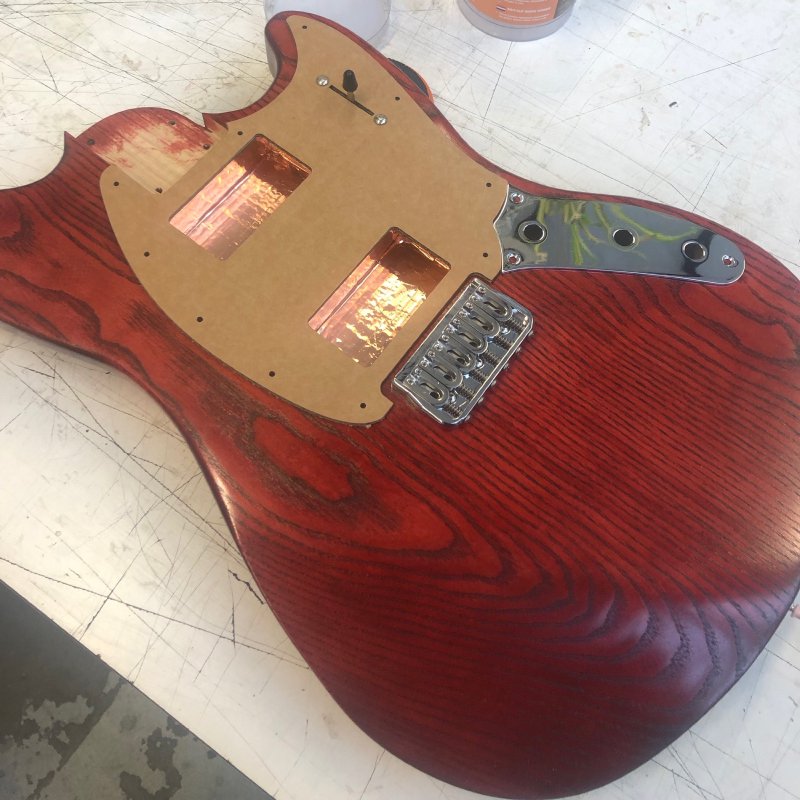
Cavities lined, I then did a quick mockup of the pick guard in cardboard to ensure all the sizing was correct for both placement on the body and that the holes for the pickups are correct.
As I mentioned last week, I’ve not had much luck in the past making custom pick guards on the CNC router, but for this guitar what I have in mind really needs to be done that way, so before I made the one for The Clydesdale I wanted to try cutting another one as an experiment first for a different technique, which I’ll explain below.
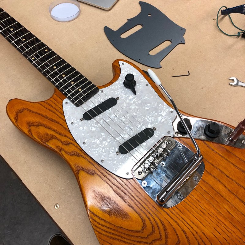
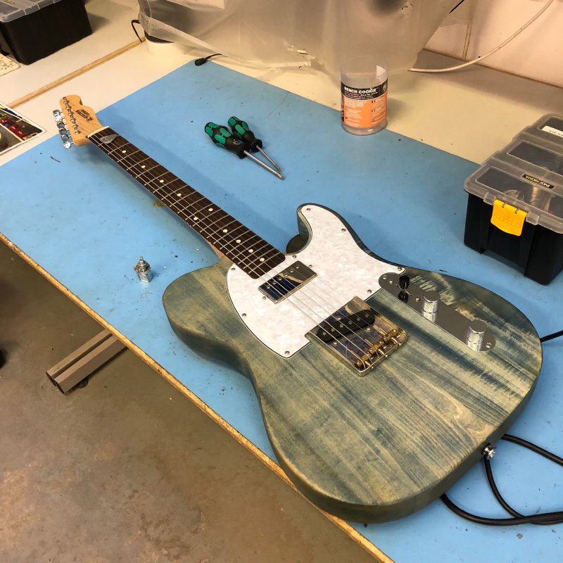
Finally, I also mounted the neck to the body this week, taking what has been two parts for so long and making them into one. To simplify the CNC process at the start of a build I don’t cut the neck on both sides using the CNC router, just from the front, which means I have to make the holes for the neck screws by hand. It’s not a major imposition (people have to do this all the time when they buy a new neck for their guitar), but given I do use an initial CNC roughing pass this sees a bit silly, and something I’ll rectify in future builds to save time. Anyway, it took me an hour or so to make sure these were lined up perfectly and straight (at this point the fretboard is rounded remember, so ensuring everything lines up isn’t just a matter of whacking the neck on the drill press and going for it).
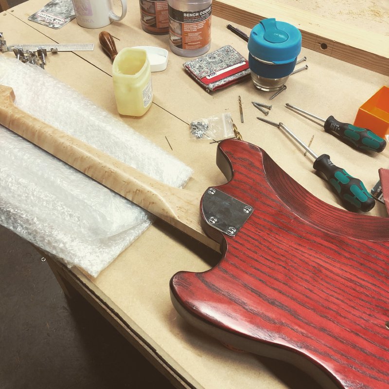
This picture makes me very happy though. The end starts to be in sight!
I mentioned last week that I had finally set up the bridge for the Prototype Offset guitar such that it would stay in tune when you used the vibrato unit. This made me happy, but I decided I wasn’t that pleased with the pick guard I’d made for it previously. Earlier in the year my attempt to made a pick guard on the CNC router had gone a bit wrong: the PVC material they’re typically made from did not sit flat (but to being quite flexible) and thus my attempt to make countersunk holes for the mount screws was a disaster. As an alternative at the time I just made one out of a duo-tone acrylic I had using the laser cutter, but now I looked at the finished guitar it just looked not up to the standard of everything else.
Thus, I decided now was time to try again, applying all the learning I’ve had on the CNC router since. The problem I faced is that if you make an angled cut on the CNC router, if the material isn’t perfectly flat then you’ll get different amounts of material removed depending on the height of the top of the material from the bed, so I need everything to be as flat as humanly possible before I start cutting.
The first thing I did before doing anything with the pick guard was to level the sacrificial bed on the CNC Router itself to make that perfectly flat again. It needed doing anyway (if you recall I last did it back in late July), and this was a motivator for me to finally get around to it. This time was much quicker, having upgraded the CNC router recently to take 1/2” shank bits we now have a 2” diameter facing off tool, rather than the 1” one I used before.
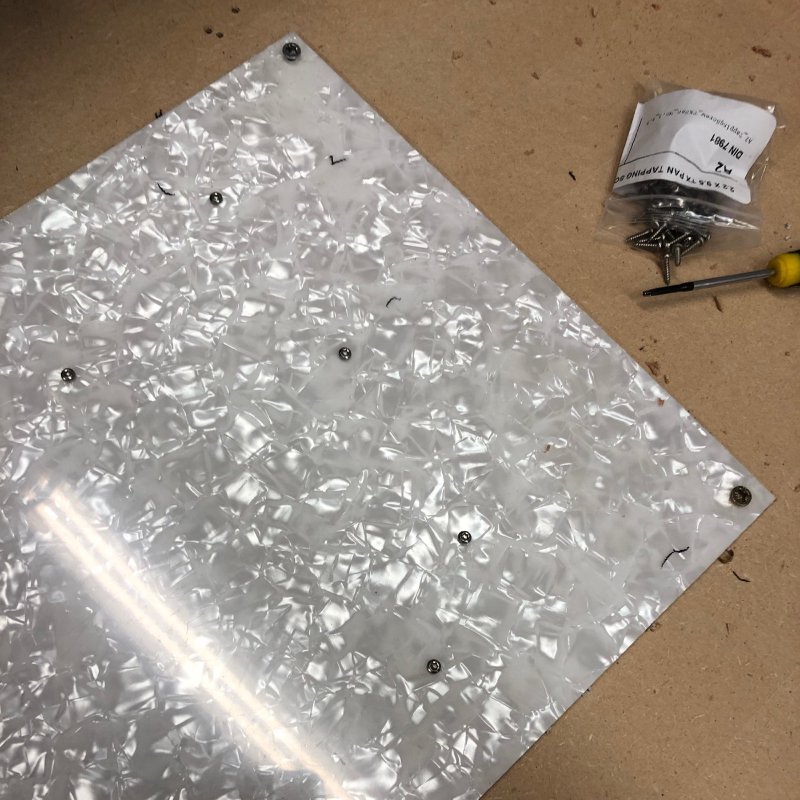
Once the bed was levelled I took my PVC material and attempted to make sure it was perfectly flat on the bed. Just screwing it in at the corners isn’t enough for a material this flexible, so I took two approaches to this. Firstly, I covered the underside of the PVC with double sided sticky tape, and stuck it to the bed, which gave me overall confidence that things would be flat. However, I didn’t quite trust the double sided tape to hold up to the CNC router’s tug alone, and so the second part of my strategy was I drilled the holes for the screws that would hold the pick guard on the guitar before I did any other cuts, and then I used those to screw the material to the CNC router bed just as I would on the guitar! These screws follow the chamfered edge and gave me as good a guarantee as I can get that this bit of the material will remain flat, and the screws themselves are small enough they’ll be clear of the cutters by a safe margin. As an added bonus, this also meant I didn’t need to use tabs when cutting the material out either, meaning no manual sanding tabs off after cutting.
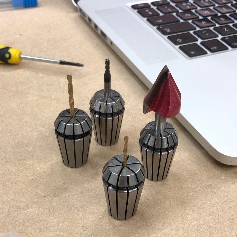
Plan down, I assembled the bits I needed for the job, can went to work: a 2mm bit for the mount holes for the guard itself, 3.5mm drill bit for the pickup mounts, a 2.5 mm end mill for the contours, and a 30˚ V-cutter to chamfer the edges.
Here you can see the results of the first pass, the material is now properly anchored down by the same screws I’ll use to attach the guard to the guitar.
And the end result was this:
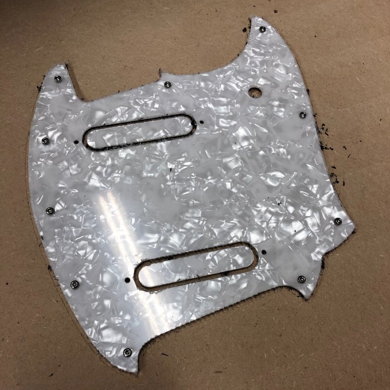
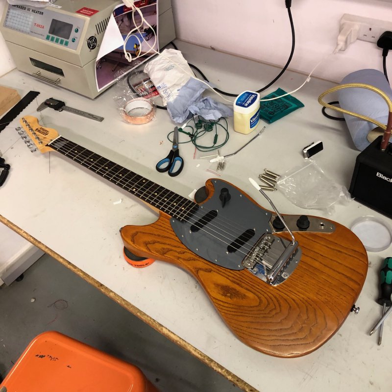
Note the bits inside the pickup holes haven’t come loose despite not being held with tabs: it turned out the double sided tape was quite effective, and the free bits did stay in place. I then had to take the guard off the bed, remove the protective film from the top which was now frayed at the edges, clear up the edges a little and peal off the tape (and wash off the remaining residue. Then it was a little work to swap the old pick guard for the new one, and the guitar now looks so much better!
I’m really pleased with how this has turned out, and also with the fact I’ve got custom pick guards licked after several failed attempts. This coming week I’ll attempt to repeat this success for The Clydesdale.
This guitar here though is now just waiting final setup before I list it for sale. If you fancy a hand built offset guitar, fitted with top quality components (House of Tone pickups, a Mastery Bridge, fitted hard case, etc.) , this get in touch. It’ll be going up on Reverb shortly I expect, priced at £1500 plus postage.
The very first guitar I built for myself still sees regular usage (indeed last week went to Rotterdam with me), and I was sad to note that the volume pot was starting to fail this week: mostly it’d be fine, but occasionally you’d whack the volume to max and it’d cut out until you rolled it back off and up again. Thankfully it’s a simple enough fix to replace the pot, and was finally the excuse I needed to give this guitar a coil split option on its humbucker.
As I’ve probably mentioned before, a humbucker pickup (the silver rectangle just under the neck in the guitar above) is actually made from two pickup coils, rather than just one as you might expect (and is common for a lot of pickups). The idea is that the two pickup coils are wound in opposite directions, so that radio interference picked up on one is picked up as a negative on the other and when you combine the signal from the two it cancels out (and thus it eliminates the “hum” you get on single coil pickups, thus the name hum-bucker).
In addition to the noise being cancelled out, because you have two coils working together you get a stronger output from a humbucker compared to a regular pickup, which is good if you want heavy rock tones, but there are times when you’d like something less juicy from your guitar. One way to achieve that is to put in a coil split, where you electrically cut out one of the coils in a humbucker and just use it as a single pickup. You risk getting the hum back then (you can see why I do the copper lining above now), but you’ll get a second tone out of your one pickup; and the more tones you can get out of a single instrument the more versatile it is, which in my book is a good thing.
To achieve a coil split you generally need your humbucker pickup to have an extra pair of wires coming out of it already to support this, and the Gibson 490R pickup in my blue tele did indeed have wiring to support this. Thus, all I needed to do was add a switch to let me toggle that extra coil on or off. What’s this got to do with the volume control you ask? Well, the conventional way to add this switch is to have a volume knob that will pull out to switch the second coil out, and push in to return it to its rightful place - so now that I needed to replace the volume control it was time to make this change! I already had the right push/pull switching pot in stock, so all I had to do was remove the old one and install the new one.
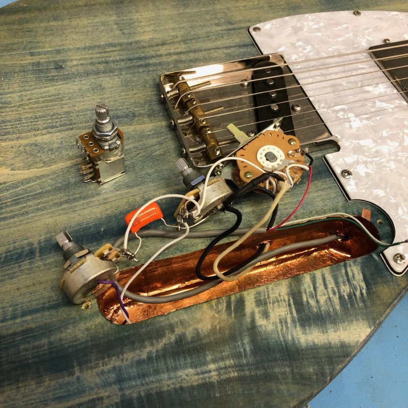
You can see here the previous wiring, and the new pot beside it with the extra solder lugs on the bottom of it to let me do the switching. My soldering must be getting better, as doing the swap was a lot quicker than I remember it was putting this guitar together back in mid 2016 when I just got started. I’m really pleased with the results: the new tone on this guitar is still clearly related to the humbucker sound, but if I want to play something a bit more nuanced then I can, but I can still run it as originally intended when I want to crank up the noise. A simple mod that gives you a bunch of flexibility.
If you’re in the Cambridge area and would like a mod like this for your guitar, do get in touch!
On the topic of circuits, it’s frustrated me that I don’t have a proper way to record existing circuits I’ve made for documentation purposes (like those in the guitar or in the amp I made) or a way to record new circuits that I come up with, so I finally sat down for a little bit and started trying to learn Autodesk Eagle. It’s early days, but I’m starting to get my head around it, despite it’s quite archaic interface. I used to work for Intel a long time ago, and back then hardware design tools always seemed to lag substantially behind other domains in terms of usability: it seems nothing much has changed in the decade and a bit that has passed since then.
Finally a little word of caution if, like me, you find yourself taking your Apple laptop into the workshop. I noticed that my laptop wasn’t charging properly at times, and that the magsafe power adapter wasn’t sitting in it’s socket quite right. I finally had a look at the socket, and it turns out it had picked up a bunch of iron shavings that had stuck to the magsafe port!
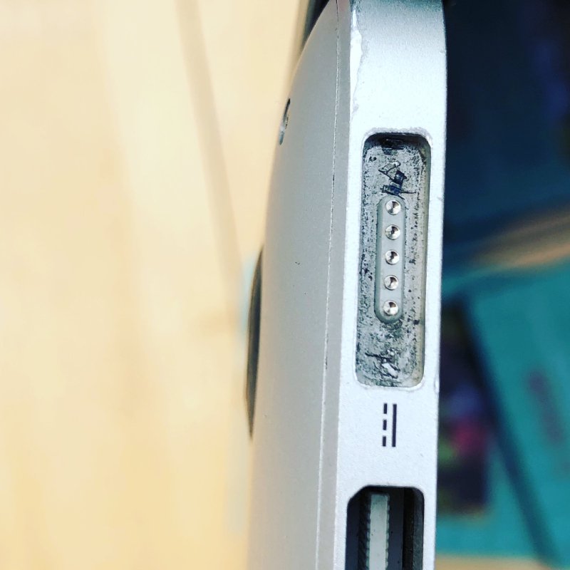
Getting them out of their wasn’t easy, as it turns out the magnet in the magsafe port is really quite strong, but once I fished them out the laptop worked a lot better :)