A week in the shop
Published 18 Jul 2018
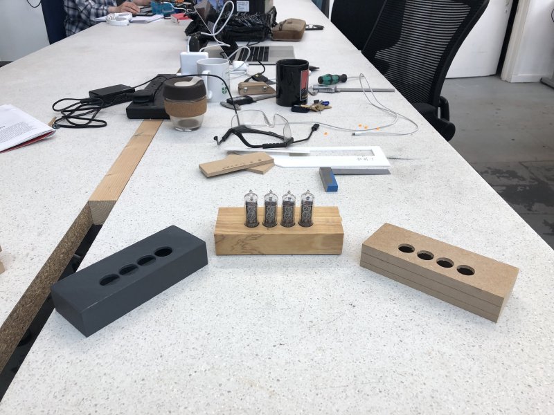
My week notes are a bit late due to a weekend spent learning how to to hunt, gather, and cook (and make fire) in a forest in Kent and doing contract software work from when I got back, but here’s a belated catch-up on the fun in the shop last week! I love this image, which pretty much covers the things I’ve been working on in the shop during that week:
Let’s start with some non-guitar design and woodwork fun. The week before last I talked about how my friend Jason was visiting, and together we were working on making a case for his nice nixie clock that he’s been building.
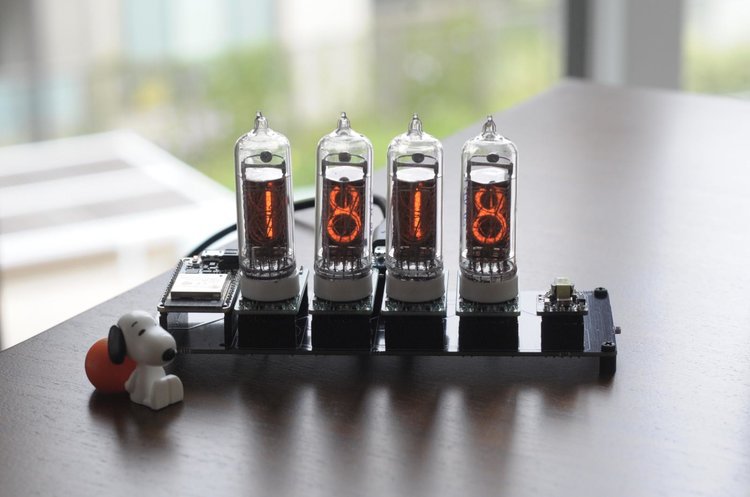
As a quick recap from that week: we’d gone through several iterations of the classic rapid prototyping flow: we had a design in Fusion 360 of the clock and the case, which we’d then 3D print using one of Makespace’s Ultimakers, which we’d test fit/measure, work out what needed changed, updated our design, print again, etc. After a few times around, we’d got to the point where we we were happy with the design and we had 3D printed case we were happy with.
We also used the laser cutter to cut a nice acrylic base for the case. Although the case looks simple (it’s just a box with some holes, right?), there’s two points of complexity in the design. Firstly, the v1 clock circuit board wasn’t really designed with the idea it’d be mounted in a case, and the layout is a little awkward for this purpose: the headers supporting some of the child boards (e.g., the left most one in the first picture) are very close to the holes where we’ll need to mount the board to the case. This, coupled with the USB port that powers the clock being almost flush with the rear of the board, means the mount posts in the box have to be very narrow and have thin walls around the screw holes, as shown here:
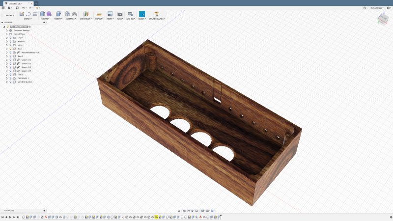
The posts look big in that picture, but are only 5 mm across and have to take a 2 mm screw, so we really don’t have much margin for error here before things won’t fit. Indeed, we’re sufficiently close that we have had to route the channel you can see above on the inside of the rear wall to let us slide the almost but not quite flush USB port into the box. The other complexity comes from the fact that the ventilation and USB port are on the rear wall, not on the top or bottom. Why is that an issue? Well, we’ll be milling the final box on the CNC router, which only works in one plane, so whilst we can hollow out the box, cut the nixie holes and the screw holes in the mount posts, we can’t use that same process to make the holes on the back, we’ll need to do those separately afterwards. Given the rear wall is only 2 mm thick (going down to 1.2 mm where the USB port channel is) we’ll need to be very careful when we eventually drill those holes in, as we risk splitting the material given how thin it is.
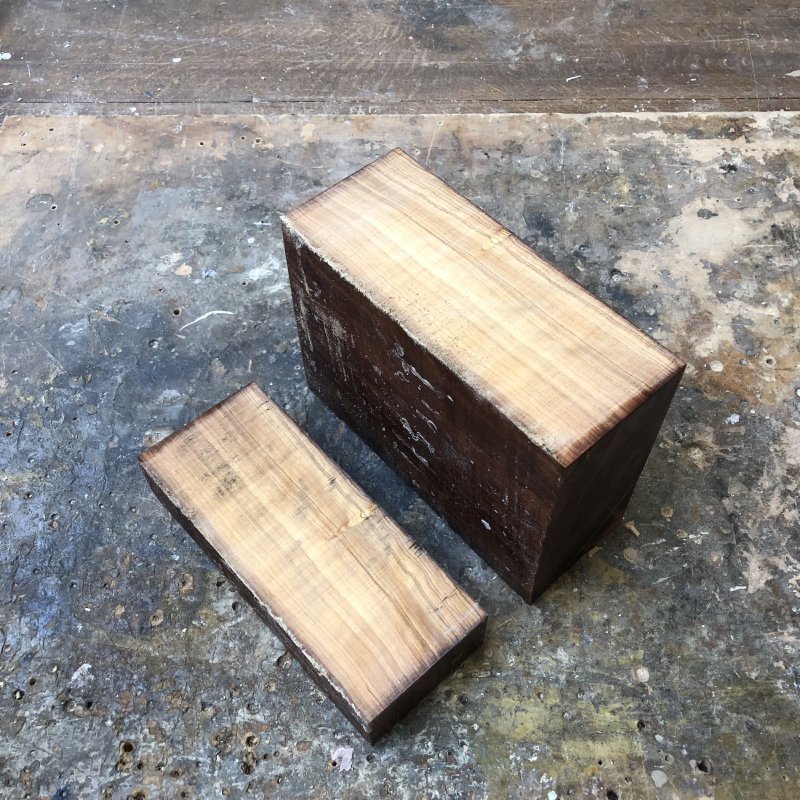
Once happy with the 3D printed designs, it was time to start thinking about making it out of wood. Jason ordered some wonderful wild olive wood from Exotic Hardwoods UK Ltd, which is possibly the nicest bit of wood I’ve ever worked with. It looks beautiful, and whilst we were working on it it made the workshop smell very nice.
The wild olive wood is as expensive as it is beautiful, and thus following our regular mantra of “measure, measure, cut”, before putting our expensive nice wood into the CNC router we first glued together a few layers of MDF I had laying around to about the correct thickness, and tested cutting out the clock case on this. People have a tendency to assume CNC routing is the easy way out: you just feed your design into a machine and press go, but it’s actually quite a labour intensive process the first time you cut a design. The CNC router is a dumb machine that will only do what you tell it; you have to use Fusion 360 to work out all the tool paths you want it to follow, use experience or trial to work out which cuts will work best in a given scenario etc. The first time I machine anything on the CNC router, although I work out all the tool paths before I enter the shop, I’m always revising the tool paths as I go as I realise assumptions I’d made about how best to approach things were wrong, or I can see a better way to get the machine to craft what I want.
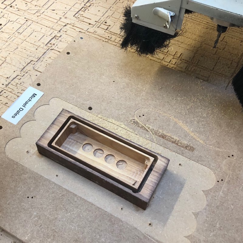
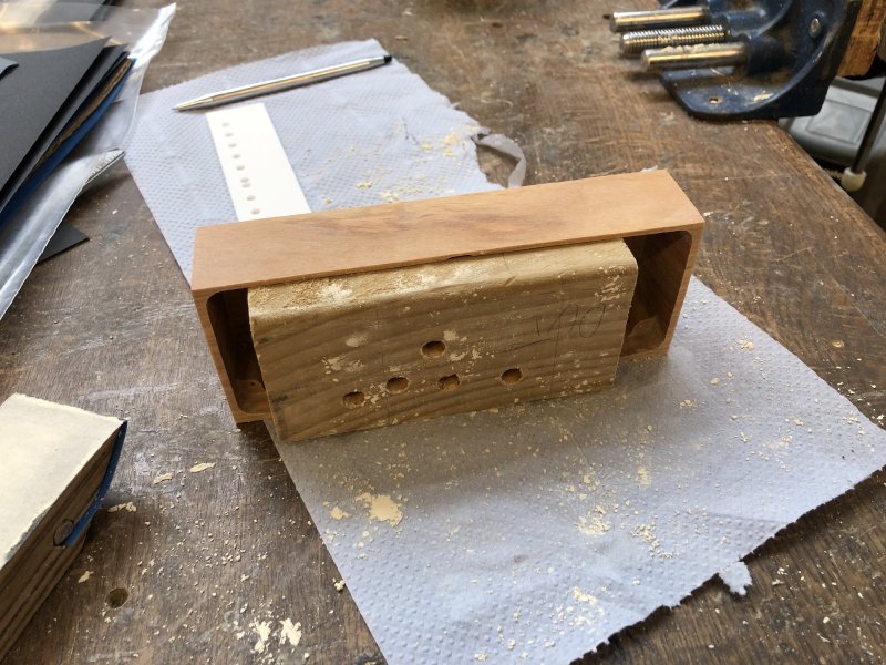
As such it took Jason and I the better part of a morning to get the first MDF version milled out:
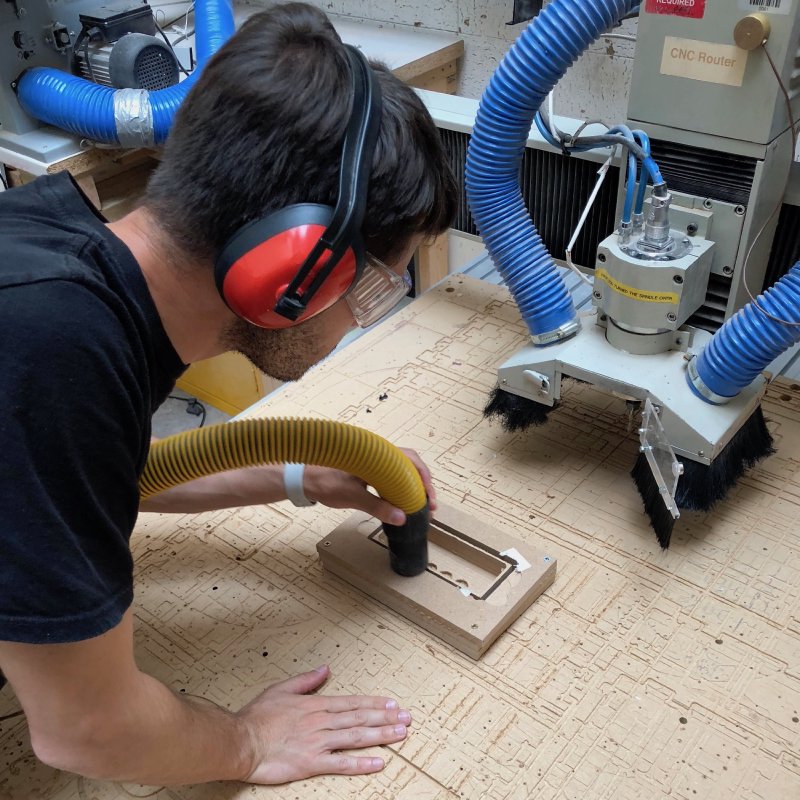
We learned a lot in this process about how to approach the milling of the wood, and we then could test fit against the actual board to check nothing had been lost in translation. We also at this point tested our plan to make the holes on the back using a laser cut template which we clamped to the back and used the pillar drill to make the actual holes. This mostly worked fine, but we learned that we needed to put a block of wood into the box whilst we drilled to stop the wood splitting given it was so thin.
Happy with our design, we then set about taking the wild olive wood and repeating the process. Even here we ended up having to tweak the design and react as we went along: we quickly realised that the harder olive wood reacted differently to being cut compared to the MDF, having a tendency to chip at the edges if we took too much off, meaning we had to go much slower with the olive wood than we had with the MDF.
Thus a few hours of tending the CNC router and on my side a lot of nerves given I know it’s not been reliable on my more complex guitar designs, we had successfully made the shape of what we hoped would be the final version of the case!
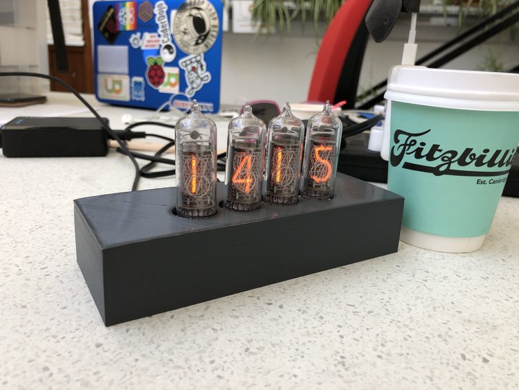
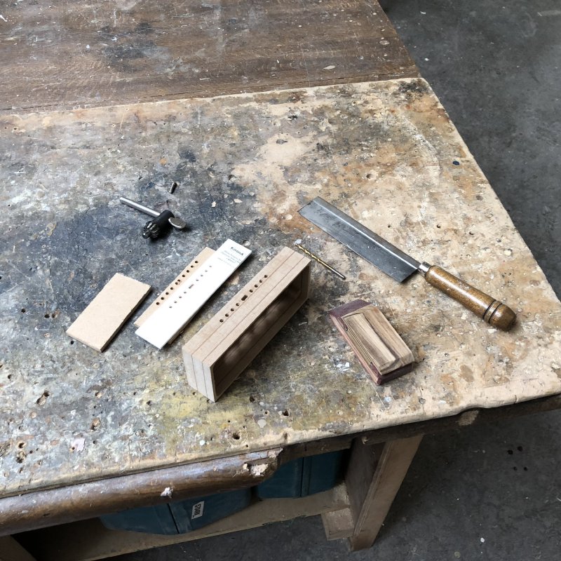
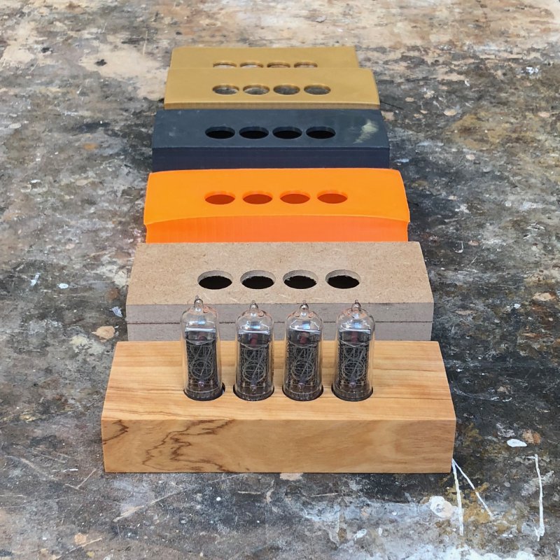
Given it was now late evening and we’d been in the workshop all day, we decided to defer cutting the rear holes until later in the week - there’s no point rushing on a job like this given the cost of a mistake will put you back to square one. Still, even if we couldn’t yet power the board on, it was nice to see another physical manifestation of the “measure, measure, cut” mantra by comparing the 3D printed version, the MDF version and the final olive wood version of the case:
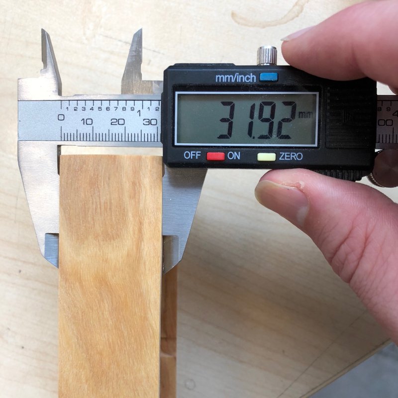
Working with an organic material like wood is full of surprises, and when two days later we came back to our case to drill the rear holes we were initially quite confused: the acrylic template we’d made for drilling the holes (and had used on the MDF version successfully) didn’t match the size of the case we’d made! More weirdly it did still match the size of the other cases, just not the final wild olive one. What was going on? We broke out the callipers, and discovered the rear of the case, which should have been 33 mm tall, was 1.2 mm shorter than expected!
(as an aside, just check out the lovely flame texture in that olive wood :)
At first we assumed perhaps we’d messed up on the CNC router, but going back to our CAM design we could see everything was good there. Only then did we check on the properties of olive wood in a wood database: it turns out wild olive wood can shrink by up to 15% in volume once cut out! The nice block of wood we’d started with was sealed in wax to prevent it shrinking, but now that we’d cut this bit of the wood free and hollowed it to a series of thin walls it’d quickly started to shrink. Luckily the board still fitted and our screw holes were still just about aligned with the board, but we decided that it was probably best that we quickly get the holes on the rear wall drilled and get to oiling the wood as soon as possible to see if we could limit further shrinkage.
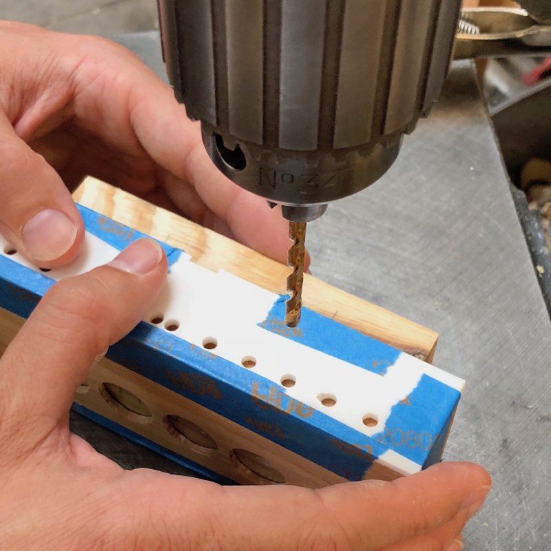
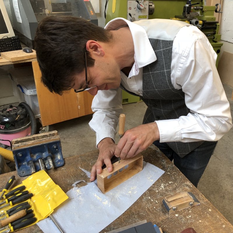
As mentioned earlier, given how thin the rear wall is, to prevent the wood splitting when we drilled the rear holes we found some scrap wood and quickly machined it (a fancy way of saying I measured it, roughed it on the band saw, and then sanded it) to the right size to make a snug fit.
We then taped on our template, noting that despite the shrinkage the internal mount posts in the case hand’t shrunk notably, so we could keep the top edge of the template flush with the top of the box and still have the USB port hole align with the mounted board.
For the USB port hole, which is small slot rather than a single circular hole, we actually just drilled two holes, one at either end of the slot, and then Jason hand filed the wood in between to make the correct gap.
After which we were able to finally do our first assembly of the box, and it looked just as lovely as we’d hoped:
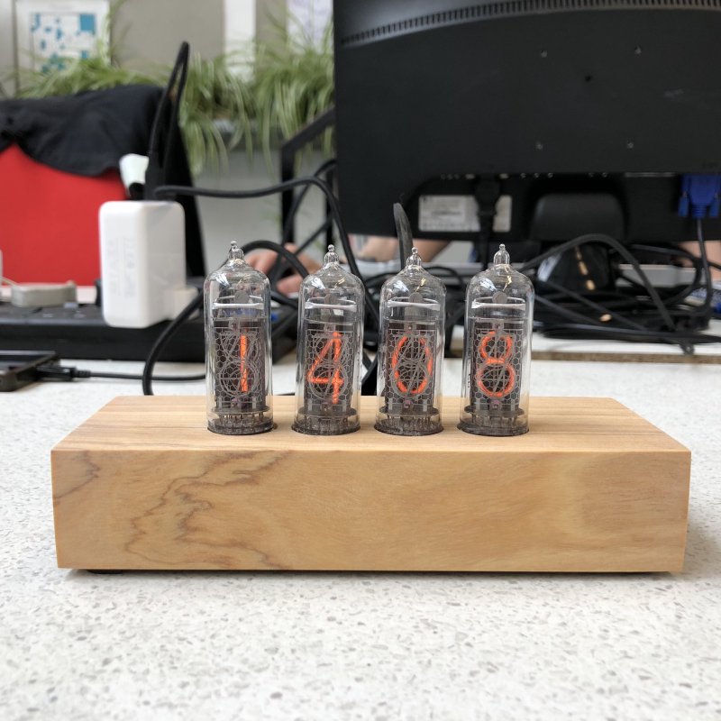
Now that the case was fully machined, we sanded it down through all the grits: from 120 grit to get rid of machining marks, all the way up to 2000 grit, at which point the wild olive feels almost like a synthetic material. This done we could start the oiling process, which took up the rest of the week. We used the same process as I use on guitar bodies and necks: applying a coat of finishing oil (I used Crimson Guitar’s finishing oil, but you can use things like tru-oil etc. to the same effect) twice a day, leaving it at least six hours to dry, and then sanding it back with 2000 grit again to get a polish on it, and repeat until happy.
Alas we ran out of time in the week to do final assembly and sign off on the clock, but we did get the case completed and Jason’s taking it back, along with all the other bits we made in Makespace that week (such as the acrylic base and the 3D printed feet) and will finish it off once he’s got the right screws etc. I very much look forward to seeing the final object in pride of place in Jason’s home!
It was a great little project to work on, I’m very grateful for Jason letting me take part in his project and proud of what we achieved in just two weeks effectively. We went from concept to a high quality, beautiful, and practical piece very quickly thanks to a combination of rapid prototyping and both Jason and I paying attention to detail throughout. I also learned a bunch about working with another kind of material, and I look forward to applying that to my guitars in the future.
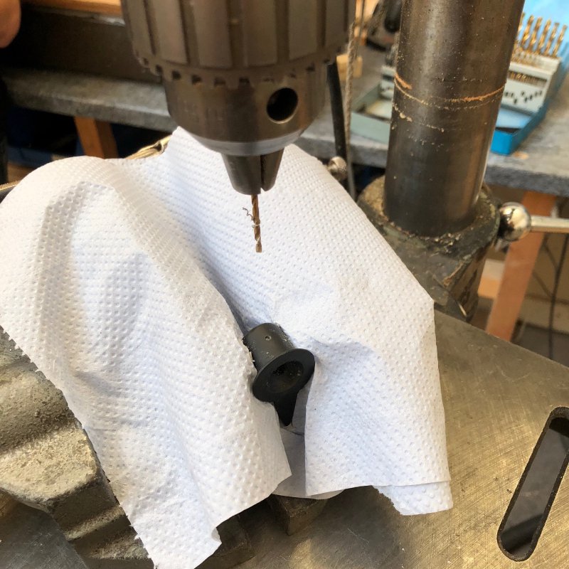
When not helping Jason with the clock case, I did managed to do various things guitar related. At the end of last week I was making another revision of the 3D printed controls for the prototype offset. Although happy with the ergonomics, I just couldn’t get the hole inside the control knobs I’d printed to mesh tightly with the knurled shaft on the control pots and rotary pickup selector switch. So I tweaked my control design and printed a new version with a hole for a grub screw in it, and I had hoped that the resin would be soft enough that I could just screw in the grub screw without tapping the hole; I was wrong. When I tried to just screw the grub screw into the hole in the resin it just split the resin near the opening and then wouldn’t go in any further.
So, it was time to skill up and learn how to tap a hole properly. For those less familiar with this term (as I was not so long ago): tapping a hole is to make the threads for the screw to follow on the inside of said hole. In a lot of cases in woodwork you don’t need to do this, you can just use self tapping screws that will cut the thread into the wood as you screw them in. But on harder materials like metal and (in this case) resin you’ll find you can’t do that, and you need to make the threads using a tap and die set.
Once again I was reminded of one of the main advantages of a communal workshop like Makespace: when I asked Alaric, one of the regular members, about where we keep the right tools he not only pointed me in the right direction, he also explained how to tap a small M3 hole like this reliably. So 5 minutes after starting, I’d taken one of the failed prints, drilled a hole of the correct size (2.8mm for a 3mm screw) tapped it, and fitted it to a pot where it remained absolutely tight. It was very much a Matrix style “I know kung-fu” moment - going from ignorance to perfectly executed in a few minutes thanks to Alaric’s guidance!
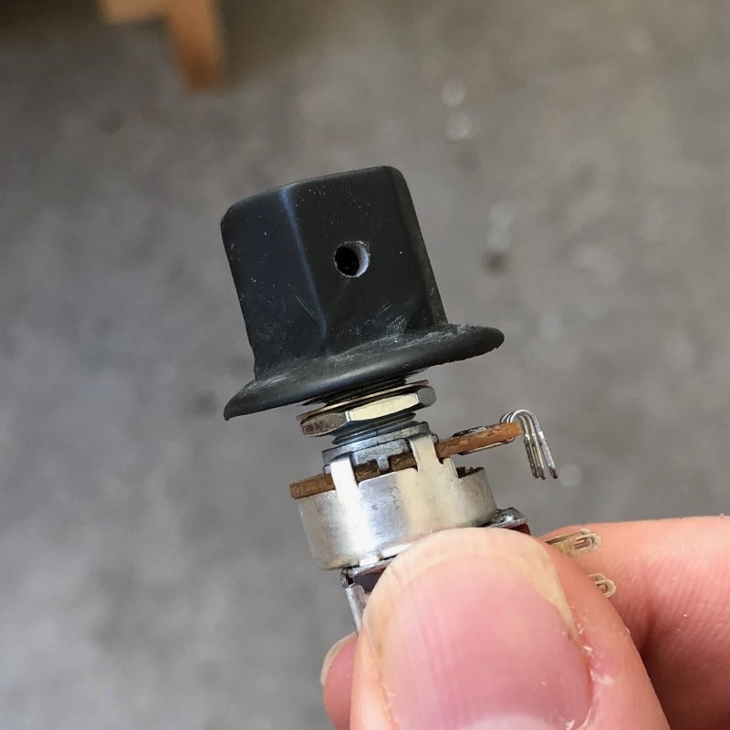
I then redid the switch on the offset with a tapped hole, fitted it with a grub screw, and it’s wonderfully secure: no more slipping when it reaches the ends of its range and you try to force it further. Very happy that I’ve learned this new skill, and that my 3D printed controls now are just as secure as they are nice to use.
Jason applied the same knowledge to the clock case, tapping the screw holes in the olive wood. Given we knew it was somewhat brittle from how it reacted when we milled it out, we felt gently tapping the holes would be easier on the wood than trying to use self tapping screws.
I’m still a little unhappy with the tuning stability on the prototype offset’s dynamic vibrato. I posted on instagram asking for advice and got a few suggestions from the kind folk there: you need at least 11 gauge strings for it to have enough tension; ensure the strings aren’t sticking in the nut by lubricating it; lubricate the posts on the vibrato; tighten the springs in the vibrato. I’m working my way through this list going from easiest to do through to more destructive (adjusting the springs will not be a nice job given how they’re bent over when fitted). But shortage of time meant I only got as far as fitting some gauge 11 strings, so I hope to revisit this in the coming days.
A lot of people tell me that the Mustang style dynamic vibrato just isn’t that stable, and that may indeed be the case, but if I’m going to sell this guitar to someone I want to know it’s setup as best it can be, so definitely want to keep at this until I know I’ve got it as good as possible. If you have any advice on setting up this style of guitar please do drop me a line!
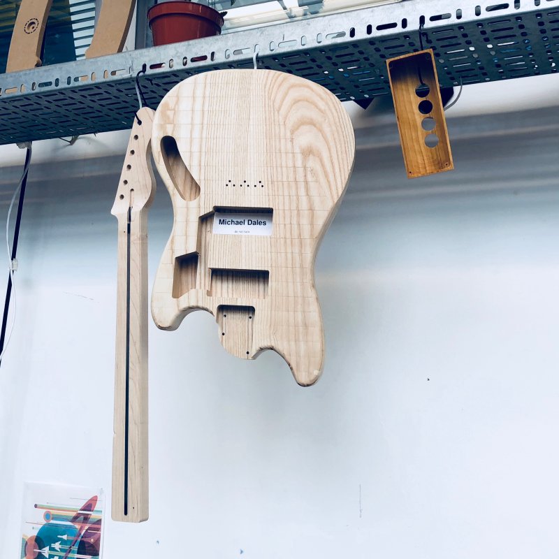
The recovered offset body got close to finished this week when I completed the shaping that the CNC router didn’t do: I used a hand router to curve over the edges, and then using a rasp I got my monthly exercise allowance by hand carving the comfort carves on the body: the arm carve on the top and the belly carve on the bottom.
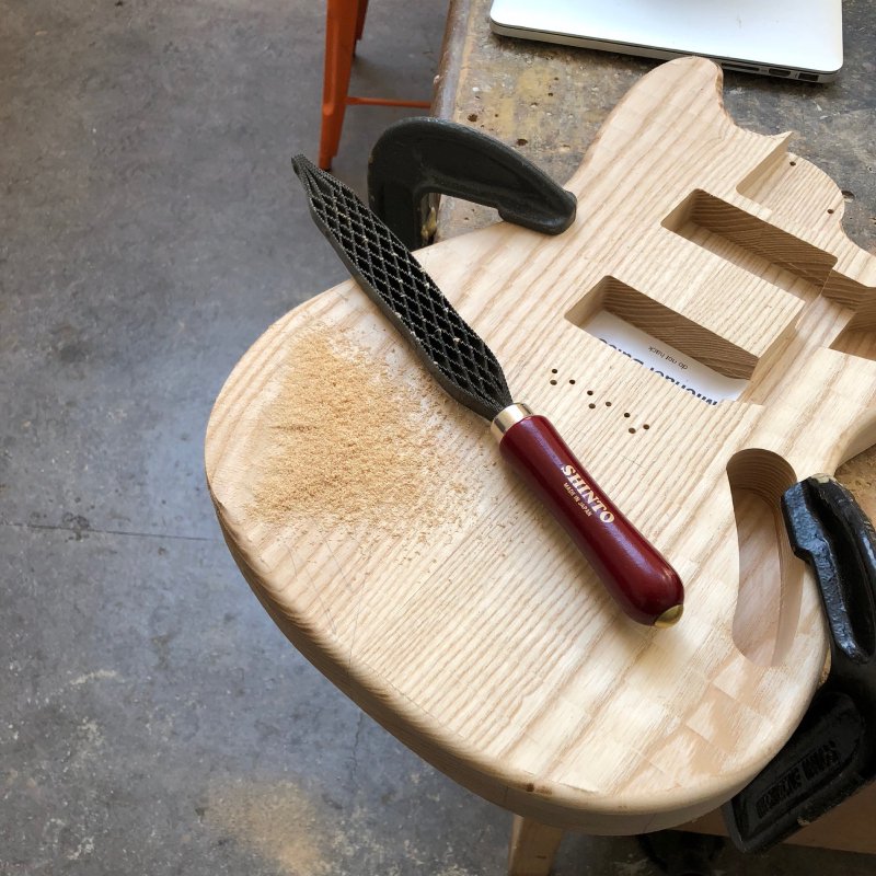
It’s a lot of effort to do this by hand, but it’s actually much easier in terms of accuracy than one might think when using such a brutal tool. I use regularly spaced pencil markings to guide me, which I refresh through out the process to ensure I almost always have some visual reference as to what I’m doing, but beyond that it’s just going slowly. This body is now done bar final sanding to remove machine marks and getting it ready to stain and oil. Having got this far, I’m now confident to cut out the delayed commission by hand rather than using the CNC router at all, which will be my first body made without using the CNC router at all. A bit of a backward step, but I’m eager to get these guitars moving and not hanging over me.