Älgen Catchup
18 Apr 2024
Tags: 3d-printing, älgen, markforged, svt
It’s been an exciting week for me, as I don’t normally end up on a video on the Swedish public broadcaster’s streaming service, SVTPlay. But this week wasn’t a normal week, so there I am!
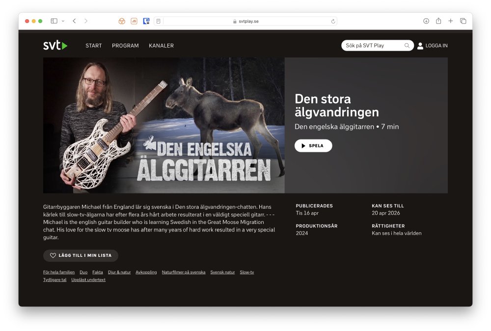
The piece is in English with Swedish subtitles, and you can watch it here. The piece is part of a trio of pieces SVT have put out ahead of this year’s Great Moose Migration which goes live next week: each year SVT broadcast from a river crossing for a few weeks in spring to catch the moose (mooses? meese?) as they migrate north, and it’s from this stream that the guitar Älgen gets its name - I designed the guitar whilst the steam was broadcasting duing the original lockdown, and the sense of place from having this live stream of a remote part of Sweden was a great part of that first lockdown for me. Anyway, more details in the program, which I recommend you watch! Nils (the man who interviewed me and structured the piece), Andrew (the camera man) and the SVT crew have done an excellent job. It was fascinating being inside something like this and seeing how much work goes into even a short production like this, but the effort was clearly worth it.
I can also heartily recommend the companion pieces: one about an artist called Pinkie who painted the meese as characters from Lord of the Rings, and then the other one on the history of the great moose migration stream (though that one is in Swedish for the most part).
So, with Älgen in my mind, it’s time to look at a little fiddling I’ve been doing on the guitar this last couple of months, as the instrument continues to evolve.
Take it to the bridge
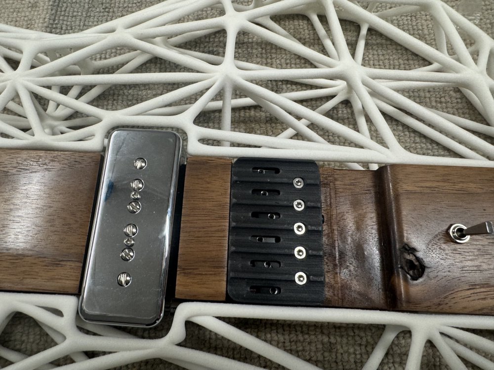
Life for the migrating meese would be a lot easier I suppose if they had a bridge, like the guitar does. The bridge is where the strings are anchored on the body, and unlike most guitars here it is also where the tuners are:
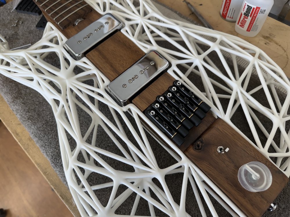
The reason the tuners are in the bridge is one of balance: with the 3D-printed body being much lighter than a wooden body, the guitar would have been very top heavy if I’d had a regular headstock with tuners at the end of it, and so I took a note from other headless guitar designs and used this as a way to ensure the centre of gravity for the guitar is where it needs to be.
Unfortunately, I’ve struggled a lot with the bridge over time, I suspect because I’m putting it into a context that it wasn’t really designed for, and it’s one of those niggles I’ve been trying to fix. Or rather, improve on the fix I did back when I was first making it.
A quick detour: intonation
To help folk understand the rest of this post, I probably need to explain what intonation is. When you design a guitar, you will pick a scale-length, which is the distance between the nut and the bridge, as shown here on one of my earlier builds:
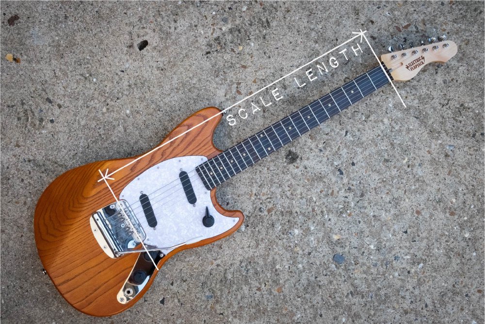
Say I make a guitar and I have all the saddles (the place the string touches down on the bridge) exactly at the scale-length, and then I put strings on and tune it up. The open strings will sound fine, but when I plan the strings one octave higher at the 12th fret, the will most likely be slightly out of tune, and worse, they’ll all be differently out of tune relative to each other. This is because string thickness and construction makes a difference, and so for a given set of strings you need to make small adjustments to the scale length to get your strings to be in tune both open and at the upper frets.
If we look at the bridge on Delfinen from last week’s notes, you’ll see that the bridge saddles are all slightly staggered for this reason:
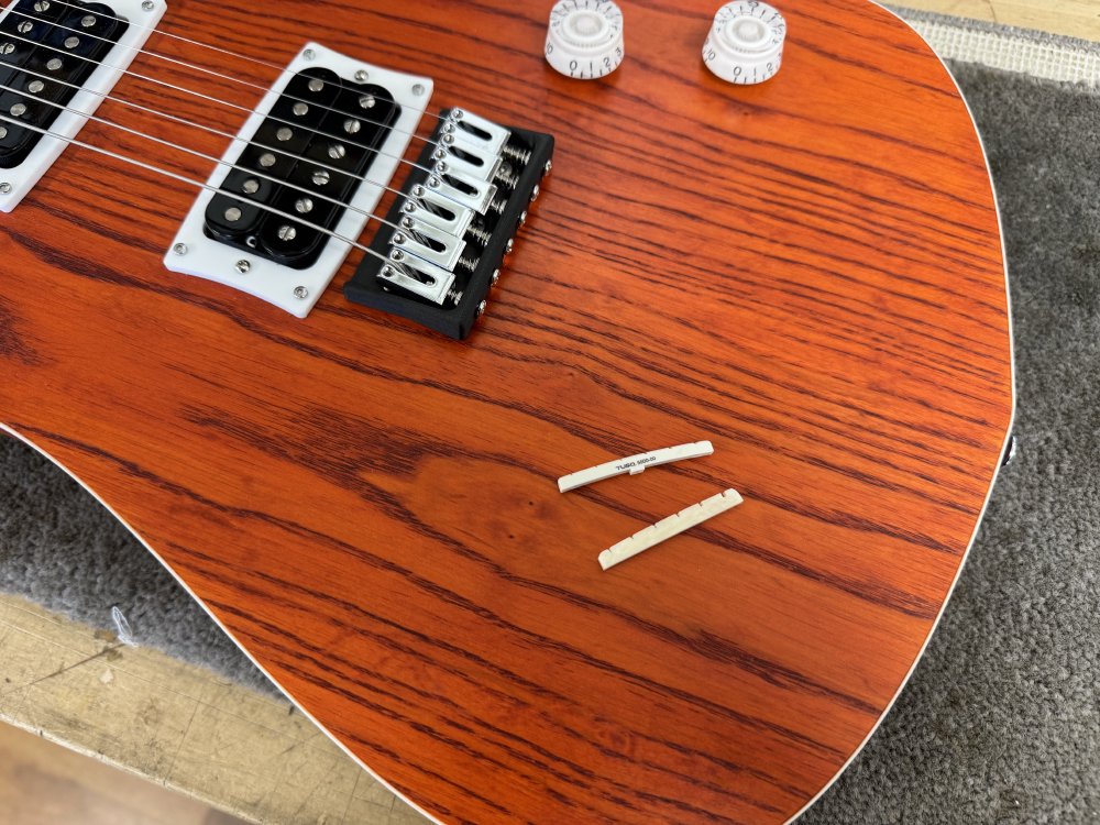
You can see there’s this thing going on where we have this zig-zag stagger on the bridge saddles: the first three are all wound strings of decreasing size, then three unwound strings of decreasing size, so not only does the diameter of the string make a change (giving you the small offset per strings) but also whether the string is wound or not makes a difference (the big change in the middle).
Once set, so long as you don’t change the gauge or style of strings, you don’t need to do much with intonation, but if you were go from say 9 gauge strings to 11 gauge strings, you’d probably want to reset your intonation again.
Back to the bridge
First I need to go back over the changes I made to the bridge I selected for Älgen back whilst I was building it, so this section is a “quick” run through what I did back when I was first building it.
The detail you need to know here for this to make sense is that the bridge I chose for Älgen isn’t one bridge, but rather six individual bridges, one per string. There’s a couple of reasons it comes that way, both of which stem from the fact that headless guitars are also often used in conjunction with styles of music that ask for 7 or 8 stringed instruments, or with multi-scale length (aka fan-fretted) instruments where each string has a different scale length, so the bridge for each string has to be set back from the one proceeding it.
So it makes sense that to address both those markets in addition to people like me who are building to a more conventional setup (six strings, fixed scale-length), that you just make each string have its own bridge, and then everyone can do what they want. I see the logic in that from the bridge-makers perspective, but it was the source of some amount of frustration during the original build.
Further to this, each per-string bridge came in two halves, the tubular top section you saw in the above photo into which the string is anchored and tuned, and then there is a bottom section which mounts to the wood and has a small sled built into it that lets you move the top section forward/backward to let you adjust the intonation.
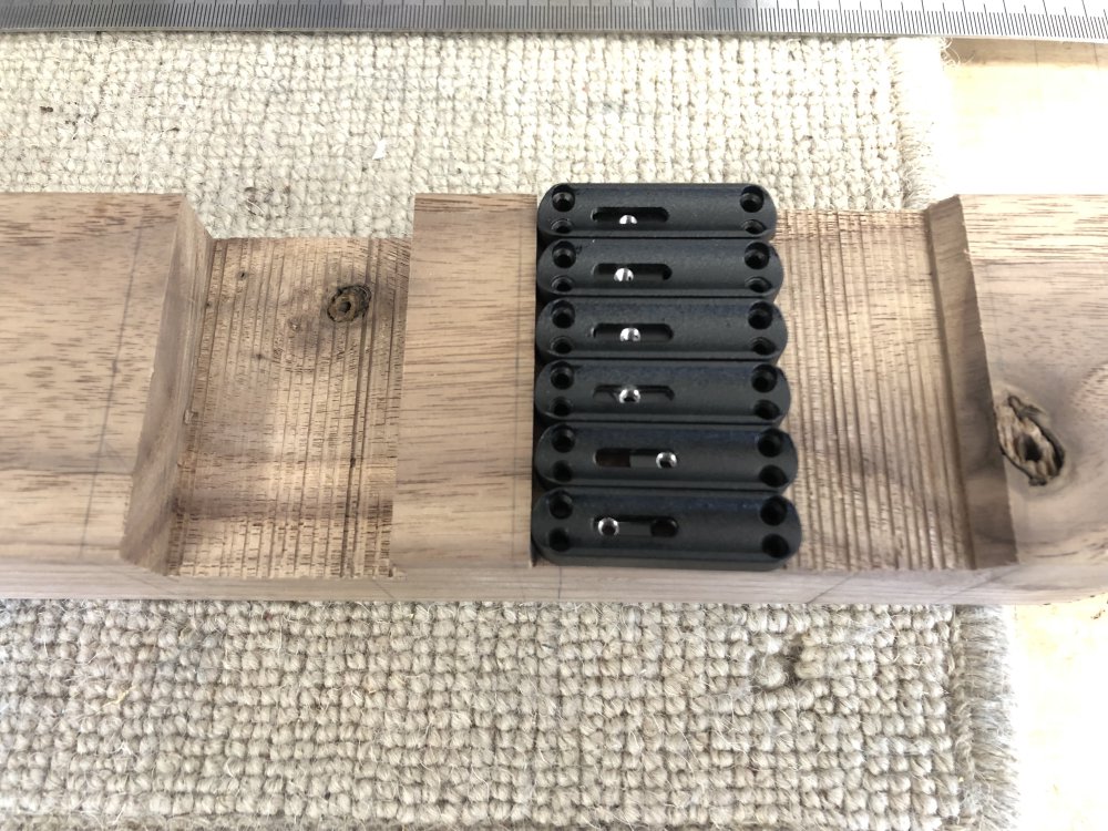
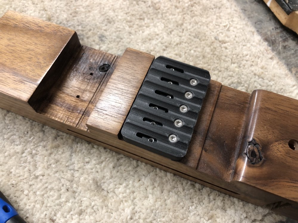
If we look closer at one of these mount pieces here, you can start to see why they were difficult to work with:
Each piece is held down by four tiny screws. This meant I had to try drill 24 perfectly aligned holes (thank goodness for laser-cutter made jigs!), and then screw in these tiny philips screws, which over time all became useless in the way philips screw heads do as they wear away. To add insult to injury, the screws are not metric in size, so getting replacements was a pain. Obviously if I was doing a multi-scale or many stringed guitar I’d be thankful of the flexibility this gives, but for me it was frustration with no real benefit.
But, I’m me, and I know how to make custom parts, so I replaced the six individual mounts with a single plate that I 3D-printed. What’s one more 3D-printed part on a guitar like this? :)
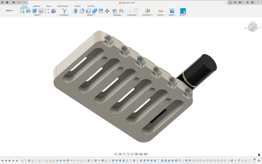
The challenge in this piece was ensuring that not only could the top parts be mounted, but also I had to make the space under the mount to have the same adjustable sleds in there to allow for intonation adjustments.
To print this I did toy with the idea of printing it in metal, as per Älgens headstock, but I decided to go with a print using the Markforged mark 2 3D-printer I had access to at the local maker-space. Prints made on this machine can use both a material called Onyx, which is a mix of nylon and carbon-fibre, which is meant to be stronger than your regular PLA or ABS print filament, and the printer can also put in solid layers of carbon-fibre, which Markforged claim give you a strength comparable to metal prints.
I was already making 3D-printed bridge plates for the regular style guitar builds this way: that’s the black part you see in the bridge in the picture of Delfinen above. Onyx alone isn’t strong enough to resist the tension of a fully tuned guitar over time, but with a triple layer of carbon-fibre in the plate I found it to be quite stable (I’ve had the prototype part I made on my daily-player for a couple of years now!).
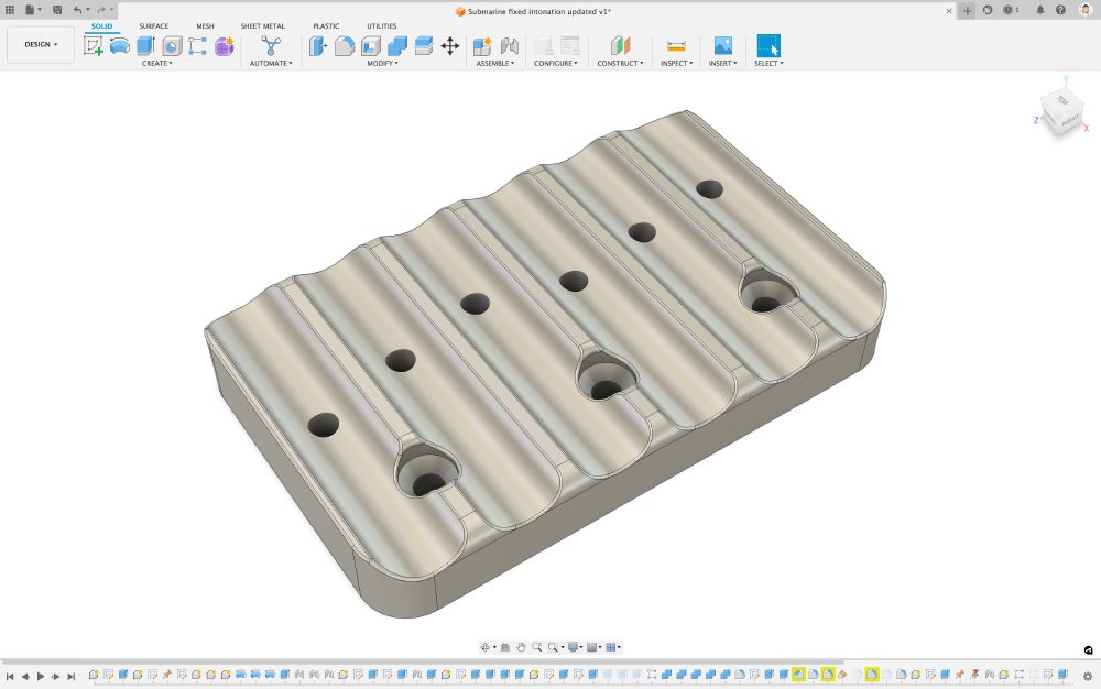
It took me a couple of goes to get the channels underneath for the sleds right, but I got there in the end:
And then with the top section mounted, all looked good:
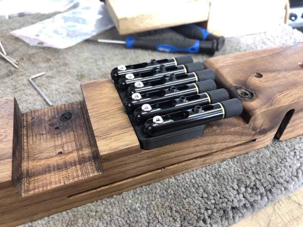
At the time this felt like success: I had a single piece that was much easier to work with, and although the finish of the print quality wasn’t the best (at least compared to Älgens other 3D-printed parts), people can’t see it once it’s in use. Job’s a good’un, as they say - or at least so I thought.
The bendy bridge
So, fast forward to a few months ago: I noticed over time my 3D-printed base for the bridge wasn’t holding flat:
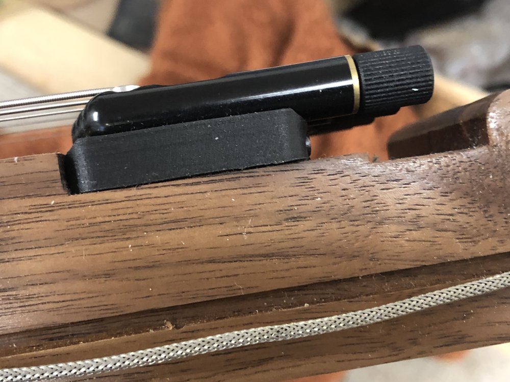
It’s not actually deflected enough to cause trouble with playing, as the strings are still tight over the saddles and those haven’t moved in height notably, but it bugged me knowing it wasn’t properly flat, and I was concerned it might get worse over time. It was one of those things that I suspect no one would even notice, but every time I looked at the guitar it’s what I thought about, and actually detracted from playing it for me, as every time I picked it up I was reminded of unfinished business.
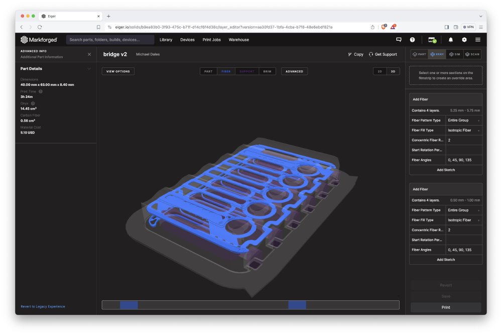
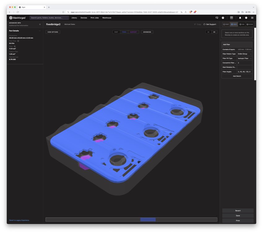
My working assumption is that the problem with this part is that the channels effectively hollow out the underside of the part, and on the top we have the slots for the top parts to mount and the screw holes, so all in all there’s not much room to get a good solid layer of carbon-fibre in the bridge. You can see in this screenshot from the Markforged software that the carbon-fibre layer, shown in blue, is very patchy (on my regular bridges I get a almost completely solid layer across the plane of the bridge plate).
My first instinct was that I should have gone with metal the first time, and to correct that mistake. However, I was a bit nervous that this might take a few iterations to get right, as I have to get those channels underneath just right size-wise: too small and the sleds don’t fit, and too large they will not align properly. Although I’ve got it right with the Markforged, moving printer and material usually means needing to tweak tolerances again, and at £100 a print, it had the potential to get costly.
But just as I was about to do this go back to metal printing, I realised there was another option here, one made possible by taking proper advantage of 3D-printing to make bespoke parts: I don’t actually need to be able to intonate this bridge. Älgen isn’t immune to needing to be intonated like any other guitar, but I’ve already intonated it for my particular set-up, and so I measure that and print a new plate that is custom to how I like my guitar. Doing this bespoke bespoke piece allows me to remove the adjustable sleds and thus remove those big gaps underneath the part, allowing a bigger continuous layer of carbon-fibre to be put down.
But what if I change the type or gauge of strings in the future? Or I go for a different tuning? In these cases I can put on the adjustable one, set things up, then print a new part for that set-up. This is the fun stuff 3D-printing opens up: not only can I make a part custom for this guitar, I can make it custom for how you want the guitar set up. Unlike metal prints, Markforged prints cost me around £12 for this part, so not the end of the world if I need to replace it or have several to hand.
In theory this makes setup changes a pain, but in practice it’s rare that I change the the things that would cause me to need to replace this, and so I think it’s a compromise I’m willing to make, or at least investigate.
Back to the drawing board
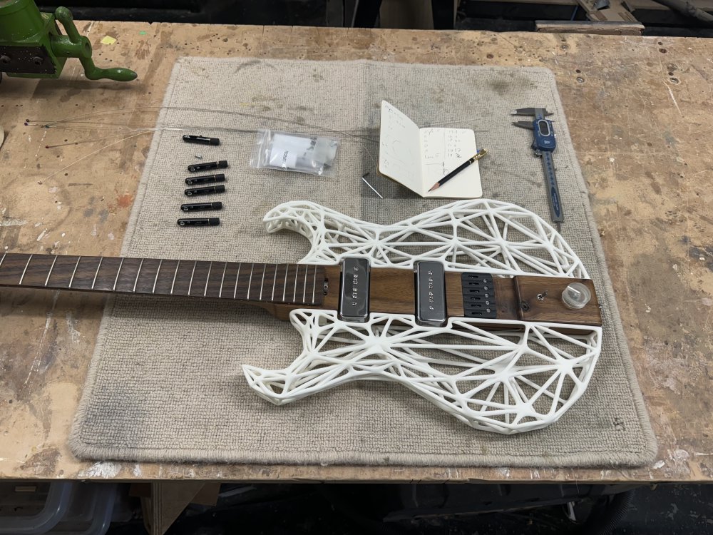
The first step, as ever, was to measure things. Here’s Älgen with the bridge top sections removed after being properly intonated:
My plan was simple: measure those mount positions, and make a print that had those offsets baked in. Thus, it was out with the callipers:
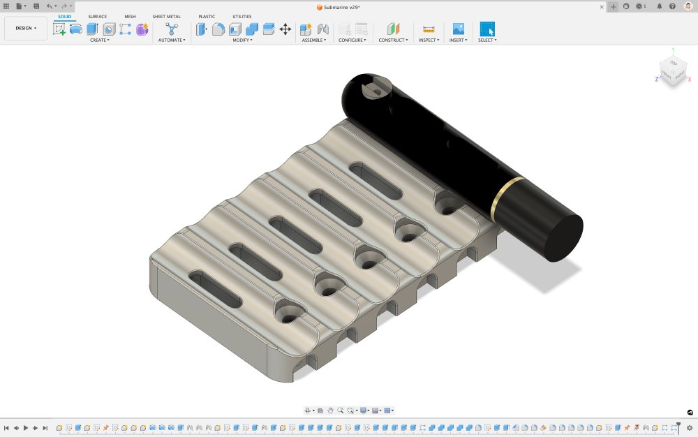
And then back to Fusion 360 to enter those into my design:
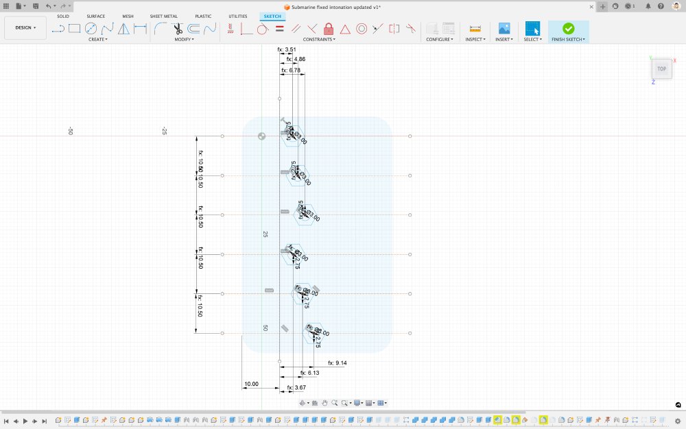
And thus I had a design for a bridge made only for Älgen, and only for when it’s got 10-46 gauge strings on it!
Throwing that back into the Markforged tool to set up the carbon-fibre layers, you can now see that I’m able to get a much bigger continuous layer inside this print:
Things then stalled for a bit due to the Markforged at the maker space playing up, but I was saved by Jonathan, who got the printer working again for me, and so I was back on track.
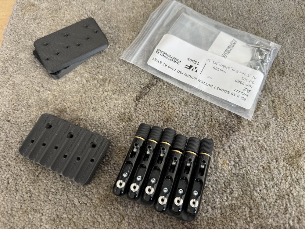
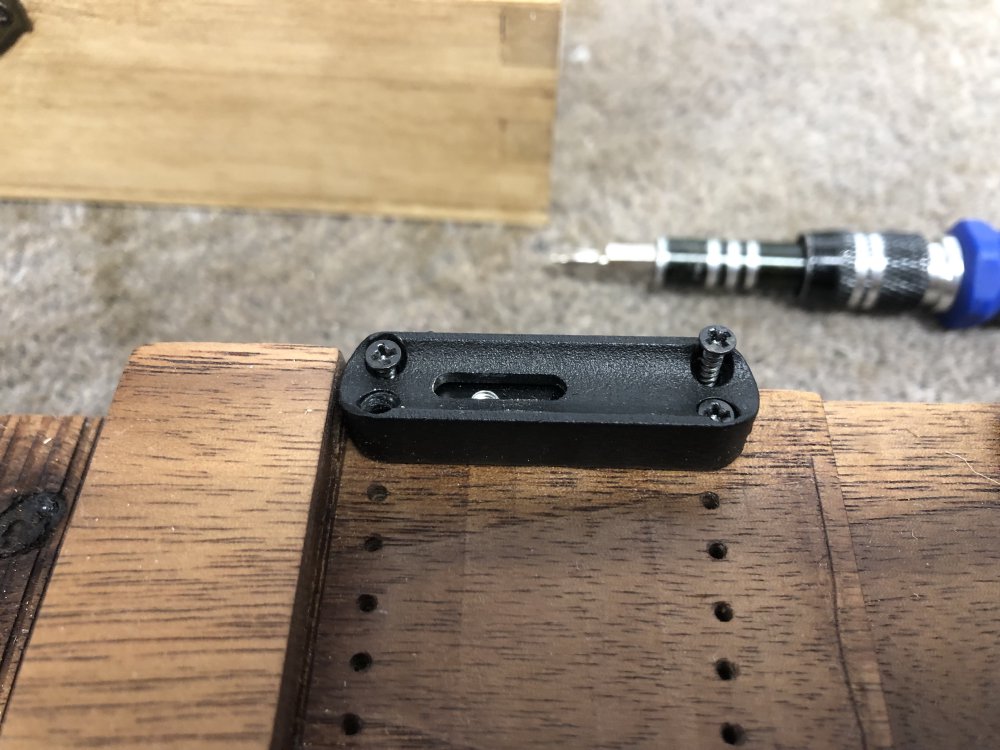
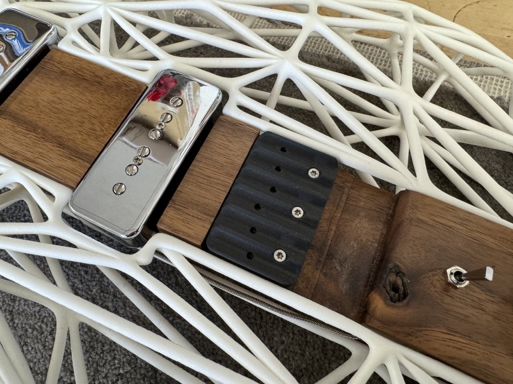
I still need a way to secure the top parts to the new bottom plate now that the sleds have gone, and for that I just used some nuts (switching the mounting bolts to metric in the process also). Ideally I’d have used threaded inserts, but the print doesn’t have much depth and I couldn’t find any small enough (the top print here is one where I didn’t get the depth for the nuts right, but it does make for a nice comparison of before/after in this photo :).
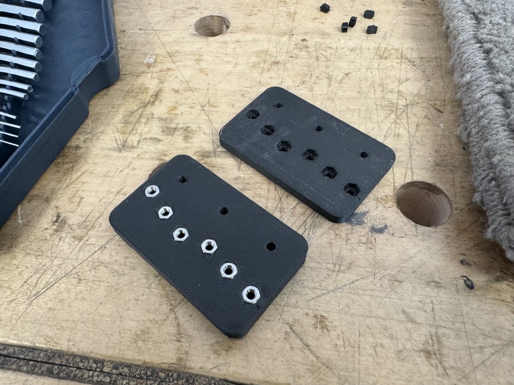
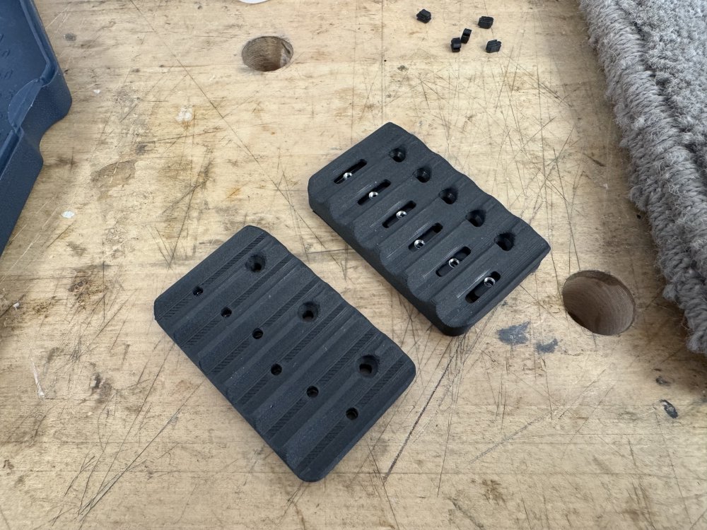
This photo shows you the old bridge plate I made and the new one, so you can see that functionally they have the same intonation set up:
This is it then mounted on Älgen:
And with the top half of the bridge pieces back on:
Success, again!
Will this work out better than the previous attempt? It’s only been a couple of weeks, so it’s hard to tell. Thus far it’s holding strong, but I’ll know for certain after say a couple of months.
I do think I perhaps should have gone for larger square nuts, just to get more surface area to resist the temptation to bend under tension, but we’ll see how it goes. That’ll be the first thing I try if this one goes, but then if that doesn’t work out I can just fall back to the metal print and know that will definitely be strong enough.
But for now, given this is a prototype and the point is to learn from it, I’m happy to push along this route with the Markforged prints. And it’s been a revelatory experience for me anyway - it has caused me to realise that I don’t fully utilise the flexibility afforded by 3D-printing, and that’s something I want to ponder on more. Yes, I can make custom parts for my guitar designs with 3D-printing, but is there more to be done in making parts that are just for one moment in the guitar’s journey, rather than for its entire life? Are there things I’m missing out on because I’ve been thinking of these parts as custom in space but not time?
And on that deep thought I shall leave it. The meese will be on SVT stream again soon: they’ve provided me with inspiration before, and so I can perhaps contemplate these questions with their assistance again!